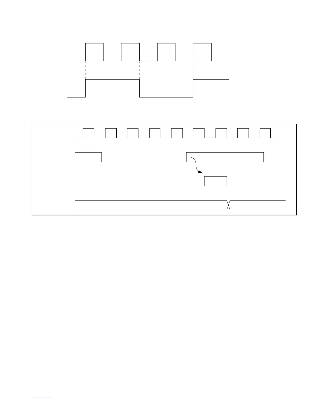
The pulse width of the external clock signal must be at least 1.5·ø clock periods. The counter will
not increment correctly if the pulse width is shorter than 1.5·ø clock periods.
10.4.2 Output Compare Timing
Setting of Output Compare Flags A and B (OCFA and OCFB): The output compare flags are
set to “1” by an internal compare-match signal generated when the FRC value matches the OCRA
or OCRB value. This compare-match signal is generated at the last state in which the two values
match, just before the FRC increments to a new value.
Accordingly, when the FRC and OCR values match, the compare-match signal is not generated
until the next period of the clock source. Figure 10-4 shows the timing of the setting of the output
compare flags.
ø
FTCI
Minimum FTCI Pulse Width
ø
External clock
source
FRC clock pulse
FRC N N + 1
Figure 10-3 Increment Timing for External Clock Input
191
Downloaded from Elcodis.com electronic components distributor

 Loading...
