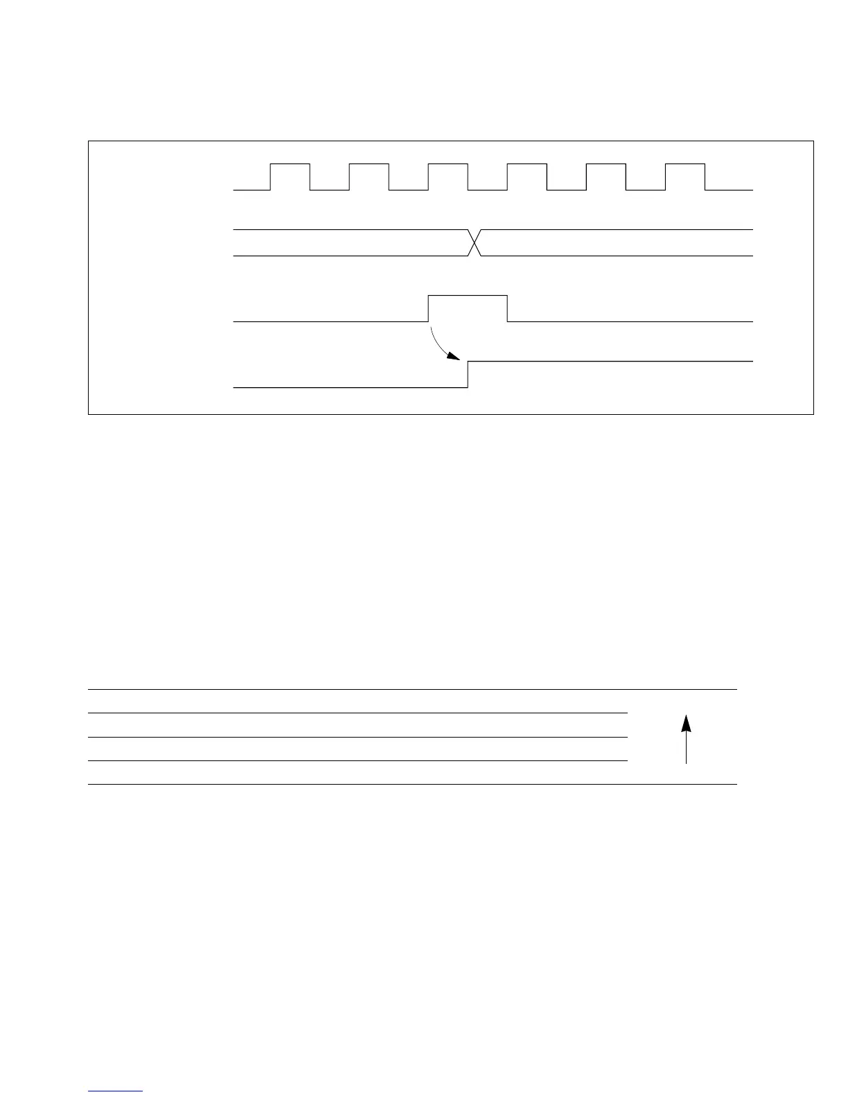
10.4.4 Setting of FRC Overflow Flag (OVF)
The FRC overflow flag (OVF) is set to “1” when the FRC overflows (changes from H'FFFF to
H'0000). Figure 10-10 shows the timing of this operation.
10.5 CPU Interrupts and DTC Interrupts
Each free-running timer channel can request four types of interrupts: input capture (ICI), output
compare A and B (OCIA and OCIB), and overflow (FOVI). Each interrupt is requested when the
corresponding enable and flag bits are set. Independent signals are sent to the interrupt controller
for each type of interrupt. Table 10-3 lists information about these interrupts.
Table 10-3 Free-Running Timer Interrupts
Interrupt Description DTC Service Available? Priority
ICI Requested when ICF is set Yes High
OCIA Requested when OCFA is set Yes
OCIB Requested when OCFB is set Yes
FOVI Requested when OVF is set No Low
The ICI, OCIA, and OCIB interrupts can be directed to the data transfer controller (DTC) to have
a data transfer performed in place of the usual interrupt-handling routine.
When the DTC serves one of these interrupts, it automatically clears the ICF, OCFA, or OCFB
flag to “0.” See section 6, “Data Transfer Controller” for further information on the DTC.
Internal overflow
signal
OVF
FRC
ø
H’FFFF H’0000
Figure 10-10 Setting of Overflow Flag (OVF)
195
Downloaded from Elcodis.com electronic components distributor

 Loading...
