5. Mode 7
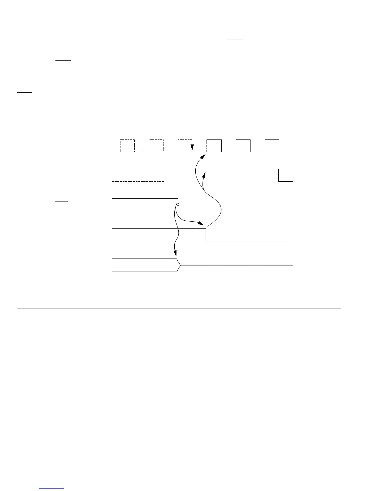
Figures E-9 and E-10 show how the pin states change when the RES pin goes Low in mode 7.
As soon as RES goes Low, all ports are initialized to the input (high-impedance) state.
The clock output pins P10/ø and P11/E are initialized 0.5 ø clock periods after the Low state of the
RES pin is sampled. Both pins are initialized to the output state.
ZTAT Versions
High impedance
RES
P1 / ø*
0
Internal reset signal
I/O ports
P1 / E*
0
*
The dotted line indicates that P10/ø and P10/E are input port if the corresponding DDR
bit is 0, but clock output pins if the DDR bit is 1.
Figure E-9 Reset during Memory Access (Mode 7)
446
Downloaded from Elcodis.com electronic components distributor

 Loading...
