9.6 Port 5
9.6.1 Overview
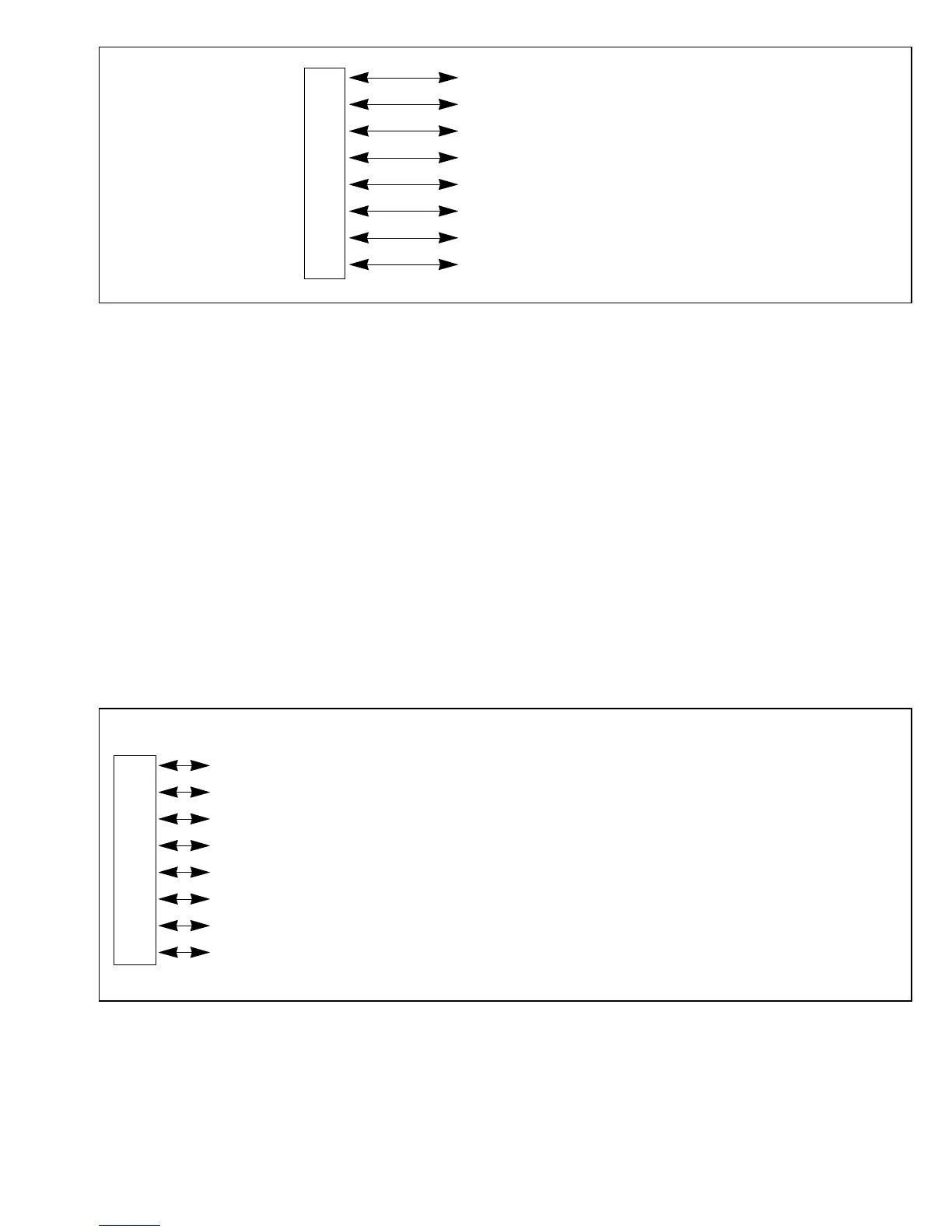
Port 5 is an 8-bit input/output port with the pin configuration shown in figure 9-11. In the
expanded modes that use the on-chip ROM (modes 2 and 4), the pins of port 5 function either as
general-purpose input pins or as bits A15 – A8 of the address bus, depending on the port 5 data
direction register (P5DDR).
Port 5 has built-in MOS pull-ups that can be turned on or off under program control.
Outputs from port 5 can drive one TTL load and a 90pF capacitive load. They can also drive a
Darlington transistor pair.
P47 (input/output)
P4
6 (input/output)
P4
5 (input/output)
Port P4
4 (input/output)
4P4
3 (input/output)
P4
2 (input/output)
P4
1 (input/output)
P4
0 (input/output)
Pin Modes 1 and 3 Modes 2 and 4 Single-Chip Mode
P5
7 / A15 A15 (output) P57 (input) / A15 (output) P57 (input/output)
P5
6 / A14 A14 (output) P56 (input) / A14 (output) P56 (input/output)
P5
5 / A13 A13 (output) P55 (input) / A13 (output) P55 (input/output)
Port P5
4 / A12 A12 (output) P54 (input) / A12 (output) P54 (input/output)
5P5
3 / A11 A11 (output) P53 (input) / A11 (output) P53 (input/output)
P5
2 / A10 A10 (output) P52 (input) / A10 (output) P52 (input/output)
P5
1 / A9 A9 (output) P51 (input) / A9 (output) P51 (input/output)
P5
0 / A8 A8 (output) P50 (input) / A8 (output) P50 (input/output)
Figure 9-10 Port 4 Pin Functions in Single-Chip Mode
Figure 9-11 Pin Functions of Port 5
157
Downloaded from Elcodis.com electronic components distributor

 Loading...
