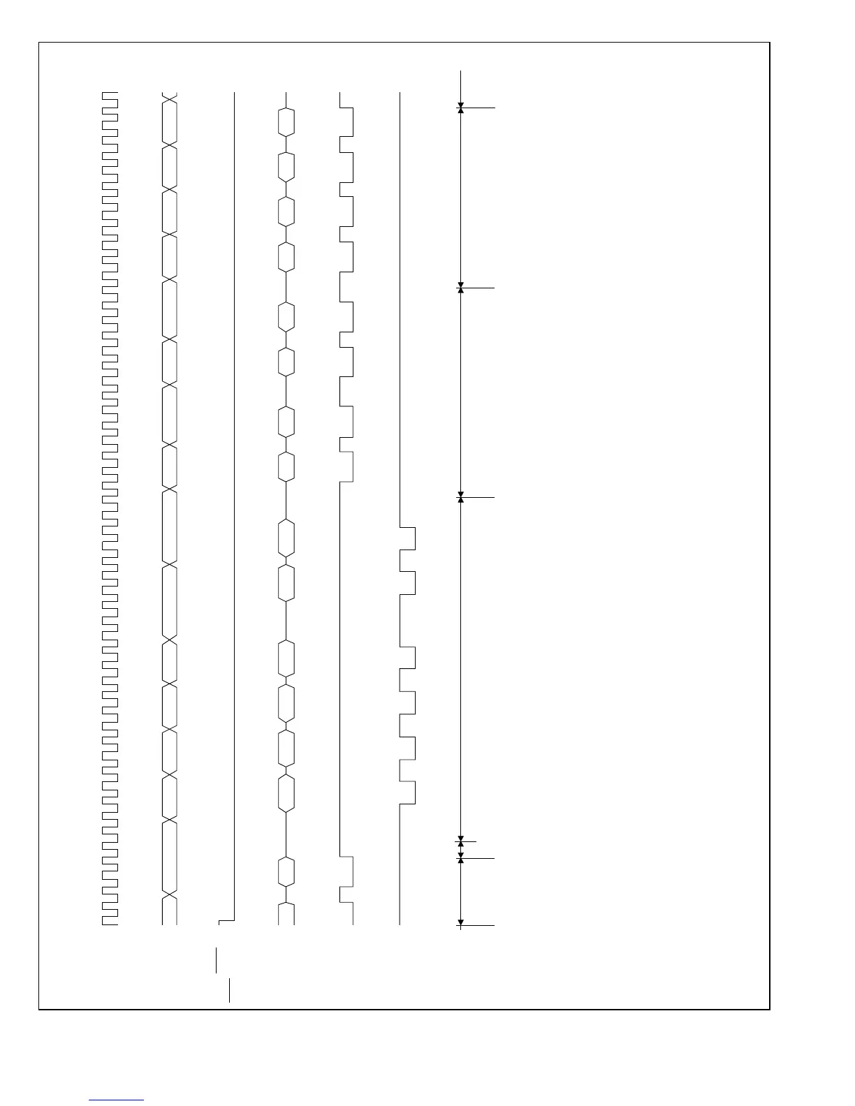
NMI, IRQ0
IRQ1
ø
Internal
address bus
Internal data
bus (16 bits)
Internal Read
signal
Internal Write
signal
Priority level
decision
and wait for
end of
current
instruction
(1) Instruction prefetch address
(2) Instruction code
(3) Starting address of interrupt-handling routine
(4) First instruction of interrupt-handling routine
Internal
processing
cycle
Stack access Interrupt vector Prefetch first instruction of
interrupt-handling routine
Start
instruction
execution
Note: This timing chart applies to the maximum mode when the program and stack areas are both in external memory.
Instruction execution starts after interrupt vector fetch and 4-byte (4 bys cycles) instruction prefetch has been done.
(1) (1) SP – 2 SP – 1 SP – 4 SP – 3 SP – 6 SP – 5 Vector Vector
address address + 1 address + 2 address + 3
Vector Vector (3)
(2) (2) PC
H PC L CP SR LSR H
don’t
care
Vector Vector Vector (4)
don’t
care

 Loading...
