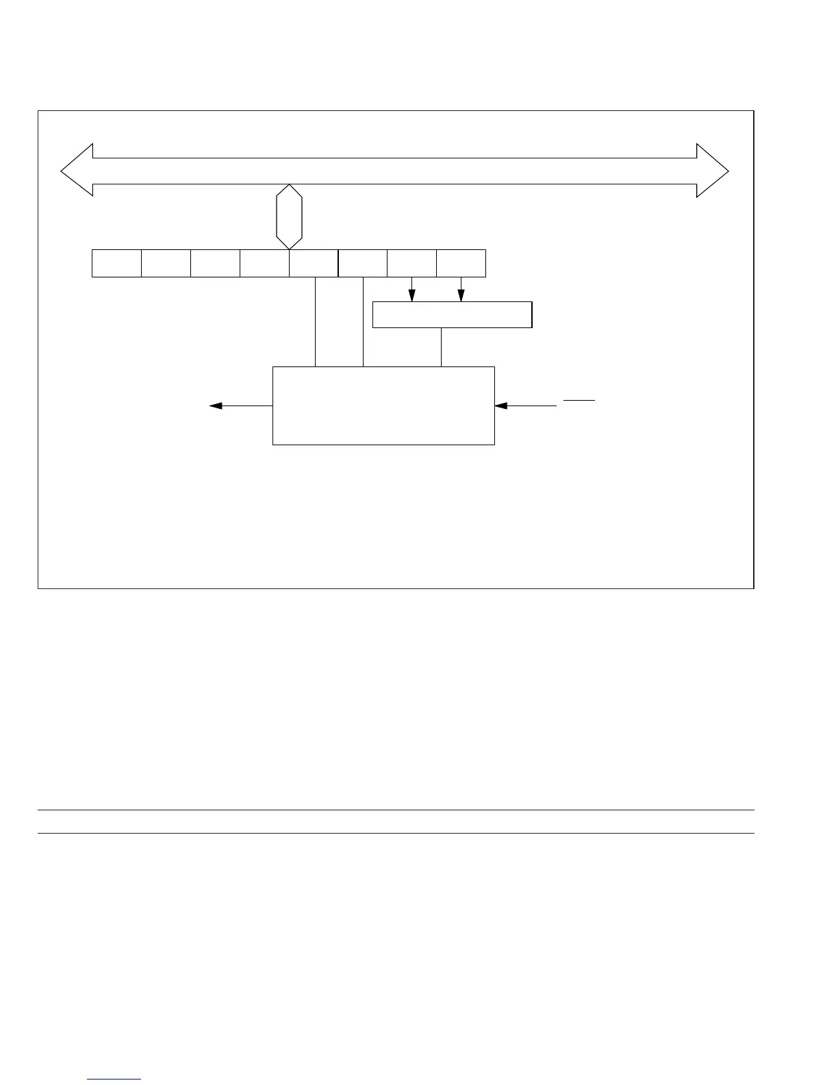
7.1.2 Block Diagram
Figure 7-1 shows a block diagram of the wait-state controller.
7.1.3 Register Configuration
The wait-state controller has one control register: the wait-state control register described in
table 7-1.
Table 7-1 Register Configuration
Name Abbreviation Read/Write Initial Value Address
Wait-state control register WCR R/W H'F3 H'FFF8
Internal data bus
WAIT input
WCR:
WMS1, 0:
WC1, 0:
Control logic
WCR
————WMS1 WMS0 WC1 WC0
Wait counter
WAIT request
Wait-state Control Register
Wait Mode Select 1, 0
Wait Count 1, 0
Figure 7-1 Block Diagram of Wait-State Controller
128
Downloaded from Elcodis.com electronic components distributor

 Loading...
