12.1.3 Input and Output Pins
Table 12-1 lists the output pins of the PWM timer module. There are no input pins.
Table 12-1 Output Pins of PWM Timer Module
Name Abbreviation I/O Function
PWM1 output PW
1 Output Pulse output from PWM timer channel 1.
PWM2 output PW
2 Output Pulse output from PWM timer channel 2.
PWM3 output PW
3 Output Pulse output from PWM timer channel 3.
DTR:
TCNT:
TCR:
Duty Register
Timer Counter
Timer Control Register
Clock
Clock
select
Internal clock source
ø/2
ø/8
ø/32
ø/128
ø/256
ø/1024
ø/2048
ø/4096
Bus interface
Internal
data bus
Module
data bus
TCR
PW
DTR
TCNT
Comparator
Output
control
Compare-
match
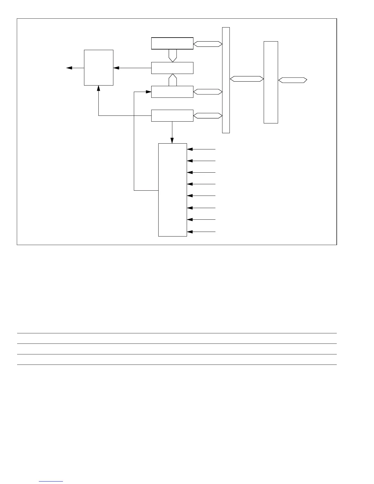
Figure 12-1 Block Diagram of PWM Timer
228
Downloaded from Elcodis.com electronic components distributor

 Loading...
