Table 14-7 Data Formats in Asynchronous Mode
SMR Bits
CHR PE STOP Data Format
0 0 0 START 8-Bit data STOP
0 0 1 START 8-Bit data STOP STOP
0 1 0 START 8-Bit data P STOP
0 1 1 START 8-Bit data P STOP STOP
1 0 0 START 7-Bit data STOP
1 0 1 START 7-Bit data STOP STOP
1 1 0 START 7-Bit data P STOP
1 1 1 START 7-Bit data P STOP STOP
Note:
START: Start bit
STOP: Stop bit
P: Parity bit
2. Clock: In the asynchronous mode it is possible to select either an internal clock created by the
on-chip baud rate generator, or an external clock input at the SCK pin. Refer to table 14-6.
If an external clock is input at the SCK pin, its frequency should be 16 times the desired baud
rate.
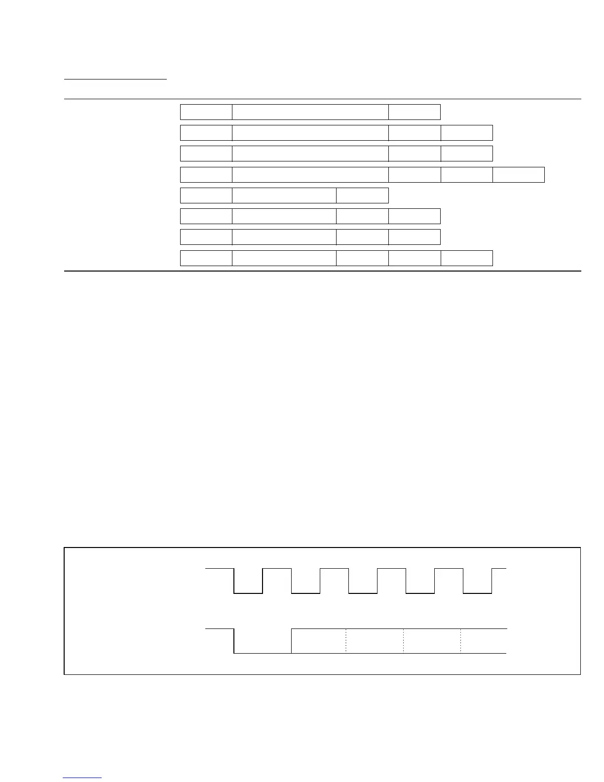
If the internal clock provided by the on-chip baud rate generator is selected and the SCK pin is
used for clock output, the output clock frequency is equal to the baud rate, and the clock pulse
rises at the center of the transmit data bits. Figure 14-3 shows the phase relationship between
the output clock and transmit data.
Output clock
Transmit data Start bit D0
D1 D2
Figure 14-3 Phase Relationship between Clock Output and Transmit Data
261
Downloaded from Elcodis.com electronic components distributor

 Loading...
