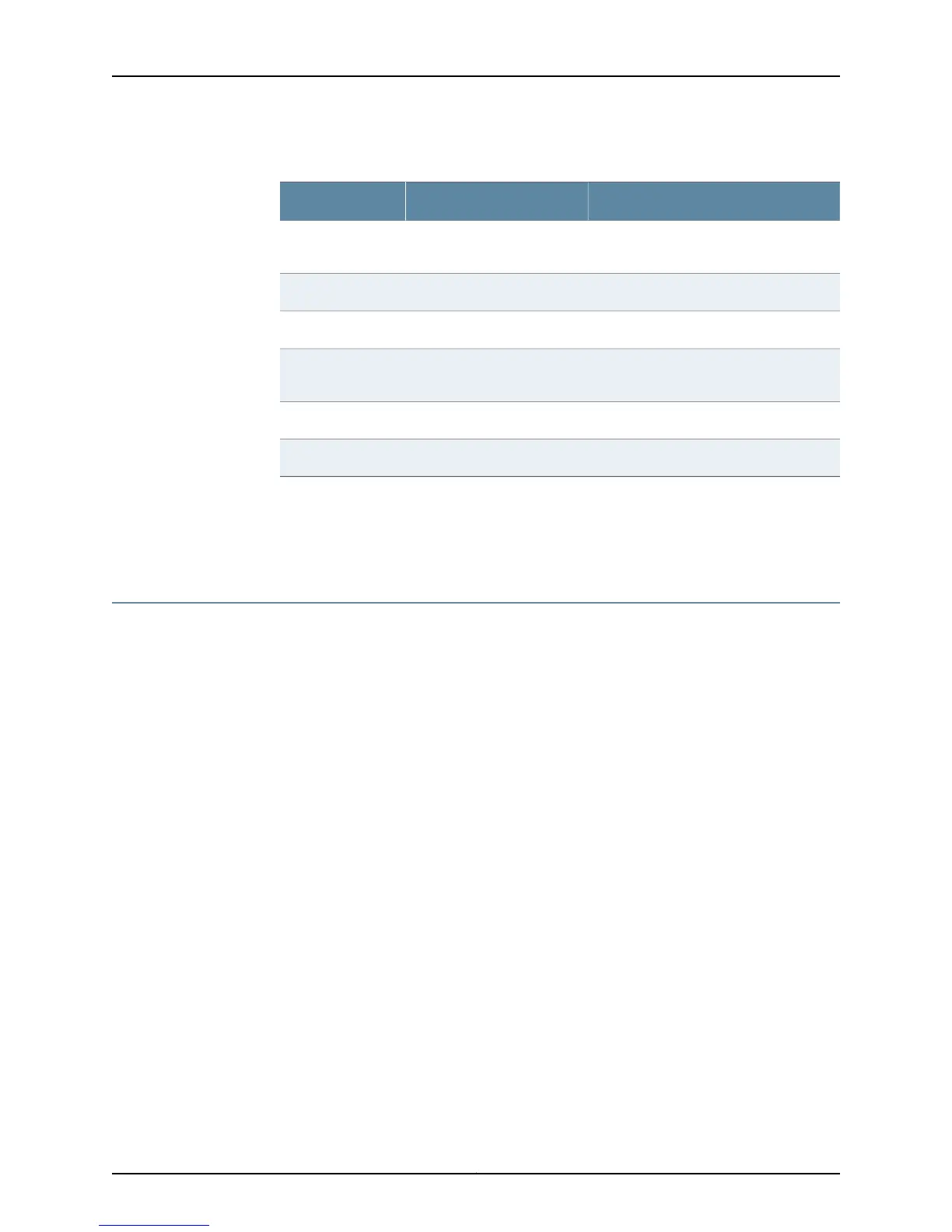
Table 92: Advertising Action Taken Following Best Route Selection
Action TakenSAFI Negotiated with PeerBest Route
Advertises unlabeled route.SAFI 1 and SAFI 4 (unlabeled
and labeled)
Unlabeled
Advertises unlabeled route.SAFI 1 (unlabeled)Unlabeled
Withdraws labeled route.SAFI 4 (labeled)Unlabeled
Advertises labeled route.SAFI 1 and SAFI 4 (unlabeled
and labeled)
Labeled
Withdraws unlabeled route.SAFI 1 (unlabeled)Labeled
Advertises labeled route.SAFI 4 (labeled)Labeled
BGP sends a route-refresh message for each SAFI that it has negotiated with a peer. For
example, if a speaker has negotiated both SAFI 1 and SAFI 4 with a particular peer, then
when you issue the clear ip bgp neighbor soft-in command, BGP sends two route-refresh
messages to this neighbor, one for each SAFI.
Providing Internet Access to and from VPNs
Normally, hosts in a VPN cannot communicate with hosts in the Internet because the
routing table in a VRF contains only routes to sites in the VPN and not routes to sites in
the Internet. The exchange of traffic between a VPN and the Internet requires both of
the following:
•
Traffic flow from the VPN to the Internet
•
Traffic flow from the Internet to the VPN
The most common, and simplest, method for providing Internet access is to configure
two separate logical circuits. One logical circuit runs between the CE router and the VRF
and is used for VPN traffic. The other logical circuit runs between the CE router and the
parent VR of the VRF and is used for Internet traffic. These logical circuits are typically
FR circuits, ATM circuits, or VLANs.
The following sections describe alternative methods of providing Internet access for
situations in which having two separate logical circuits is not acceptable or desirable.
Enabling Traffic Flow from the VPN to the Internet
Traffic from a CE router arrives on a PE interface that exists in the context of a VRF. The
PE router then looks up the destination address of the IP packet in the context of the
VRF routing table rather than the VR routing table.
Problems
The VRF routing table lookup introduces the following complication.
461Copyright © 2010, Juniper Networks, Inc.
Chapter 6: Configuring BGP-MPLS Applications
 Loading...