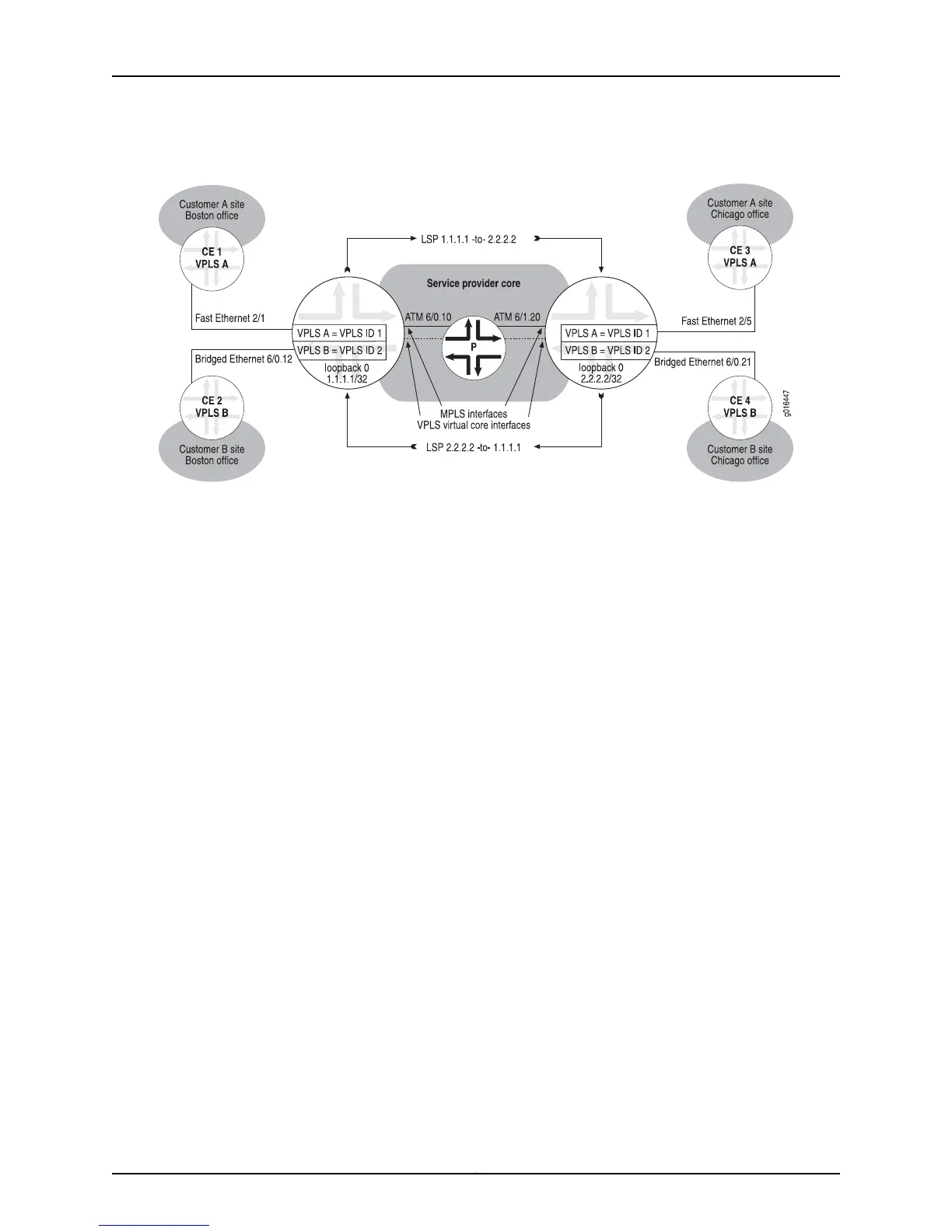
Figure 130: Topology for VPLS Configuration Example with LDP Signaling
PE 1
Default virtual router
PE 2
Default virtual router
•
Topology Overview of VPLS with LDP Signaling on page 606
•
Configuration on PE 1 (Local PE Router) on page 606
•
Configuration on PE 2 (Remote PE Router) on page 607
Topology Overview of VPLS with LDP Signaling
Because the basic components of a VPLS network are the same regardless of whether
BGP signaling or LDP signaling is used, the sample topology shown for LDP signaling in
Figure 130 on page 606 is almost identical to the sample topology shown for BGP signaling
in Figure 129 on page 599. Figure 130 on page 606 includes two VPLS domains: VPLS A,
which connects CE 1 and CE 3, and VPLS B, which connects CE 2 and CE 4. The local PE
router, PE 1, and the remote PE router, PE 2, each participate in both the VPLS A domain
and the VPLS B domain, and have one VPLS instance associated with each domain
configured on each router.
Unlike a VPLS configuration with BGP signaling, a VPLS configuration with LDP signaling
requires that you configure a VPLS ID for each VPLS instance to uniquely identify each
VPLS domain. In the sample topology in Figure 130 on page 606, instance vplsA is assigned
VPLS ID 1, and instance vplsB is assigned VPLS ID 2 on both the local PE router and the
remote PE router. You must also configure a list of remote neighbor (peer) addresses to
which LDP can send or from which LDP can receive targeted hello messages. In the
sample topology, the remote neighbor configured for PE 1 is PE 2 with IP address 2.2.2.2,
and the remote neighbor configured for PE 2 is PE 1 with IP address 1.1.1.1.
The Ethernet and bridged Ethernet network interfaces, ATM core-facing interfaces, VPLS
virtual core interfaces, and MPLS LSPs play the same role in a VPLS topology with LDP
signaling as they do in a VPLS topology with BGP signaling. For more information about
these components, see “Topology Overview of VPLS with BGP Signaling” on page 599.
Configuration on PE 1 (Local PE Router)
Use the following commands on the local PE router (PE 1) to configure the VPLS topology
shown in Figure 130 on page 606.
Copyright © 2010, Juniper Networks, Inc.606
JunosE 11.2.x BGP and MPLS Configuration Guide
 Loading...