3.4 Control of common rail system
(CRS) engine
The following
items are controlled by the engine ECU
as control for a common rail system engine.
1. Fuel injection quantity control
The amount of fuel injected is determined using
standard injection volume calculated based on
engine state and operating conditions.
A calibration value is added to this information
through parameters such as coolant temperature,
intake air temperature, and intake air pressure.
2. Fuel injection timing control
The engine ECU controls injection timing through
start of energization of the injectors.
First the main injection timing is determined and
next other injection timing such as pilot injections
are set.
3. Fuel injection rate control
A pilot injection enables maintaining minimum initial
fuel injection rate.
This mitigates explosive initial combustion and
reduces NOx and noise.
4. Fuel injection pressure control
Based on engine load (final injection volume and
engine speed), the engine ECU calculates the set
fuel injection pressure.
Calculated data is used to control the volume
supplied by the supply pump as well as the fuel
pressure in the rail.
3.5 Fuel tank
3.5.1 Outline of fuel tank
The fuel tank stores fuel.
3.5.2 Structure of fuel tank
The fuel tank is made up of a tank body and fuel inlet
opening.
3.5.3 Function of fuel tank
The fuel tank stores fuel.
A float
is generally provided in the tank to show the
amount of fuel remaining.
This float detects float liquid surface position and sends
a signal to a meter on the operator panel.
3.5.4 Specification of fuel tank
Tank volume is different depending on the model
equipped on.
Check the
specifications of the model equipped on for
details.
3.6 Water separator
3.6.1 Outline of water separator
The water separator removes the water included in the
fuel.
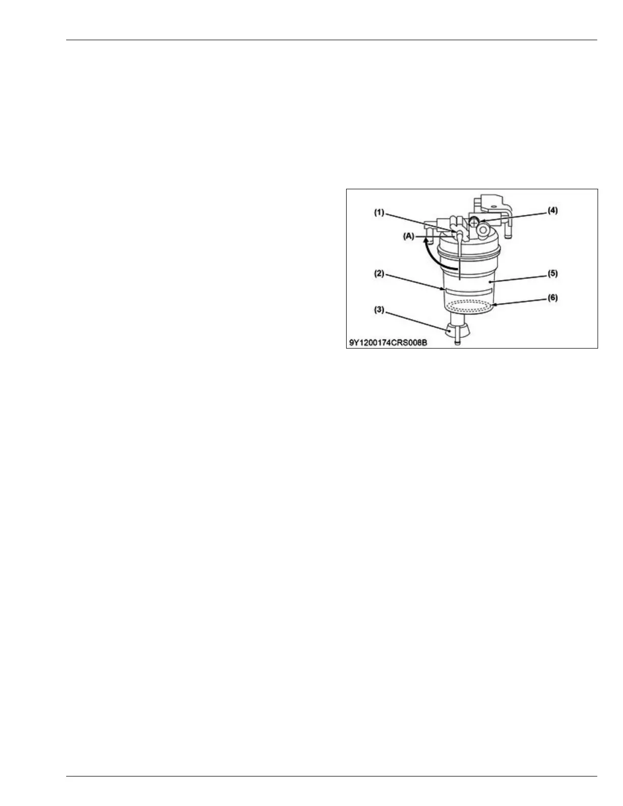
3.6.2 Structure of water separator (Type1)
The water separator (Type 1) is made up of the cup,
float, and water separator handle and the like.
(1) Water separator handle
(2) Line
(3)
Valve
(4) Screw
(5) Cup
(6) Float
(A) Close
3.6.3 Structure of water separator (Type2)
The water separator is made up of the separator body,
hand pump, and level sensor and the like.
The fuel flow direction of the water separator is set.
MECHANISM
3. Fuel system 4. ENGINE
D1803-CR-E4,D1803-CR-TE4,D1803-CR-TIE4,V2403-CR-E4,V2403-CR-TE4,V2403-CR-TE4BG,V2403-CR-TIE4
 Loading...


