5. T
ighten the crankshaft position sensor mounting
screw (5) to the specified torque.
NOTE
• If replace
the crankshaft position sensor,
measure the air gap between crankshaft
position sensor and flywheel.
Air gap
Service specifi-
cation
0.30 to 1.5 mm
0.012 to 0.059 in.
Tightening tor-
que
Crankshaft posi-
tion sensor mount-
ing screw (5)
9.81 to 11.3 N⋅m
1.00 to 1.15 kgf⋅m
7.24 to 8.33 lbf⋅ft
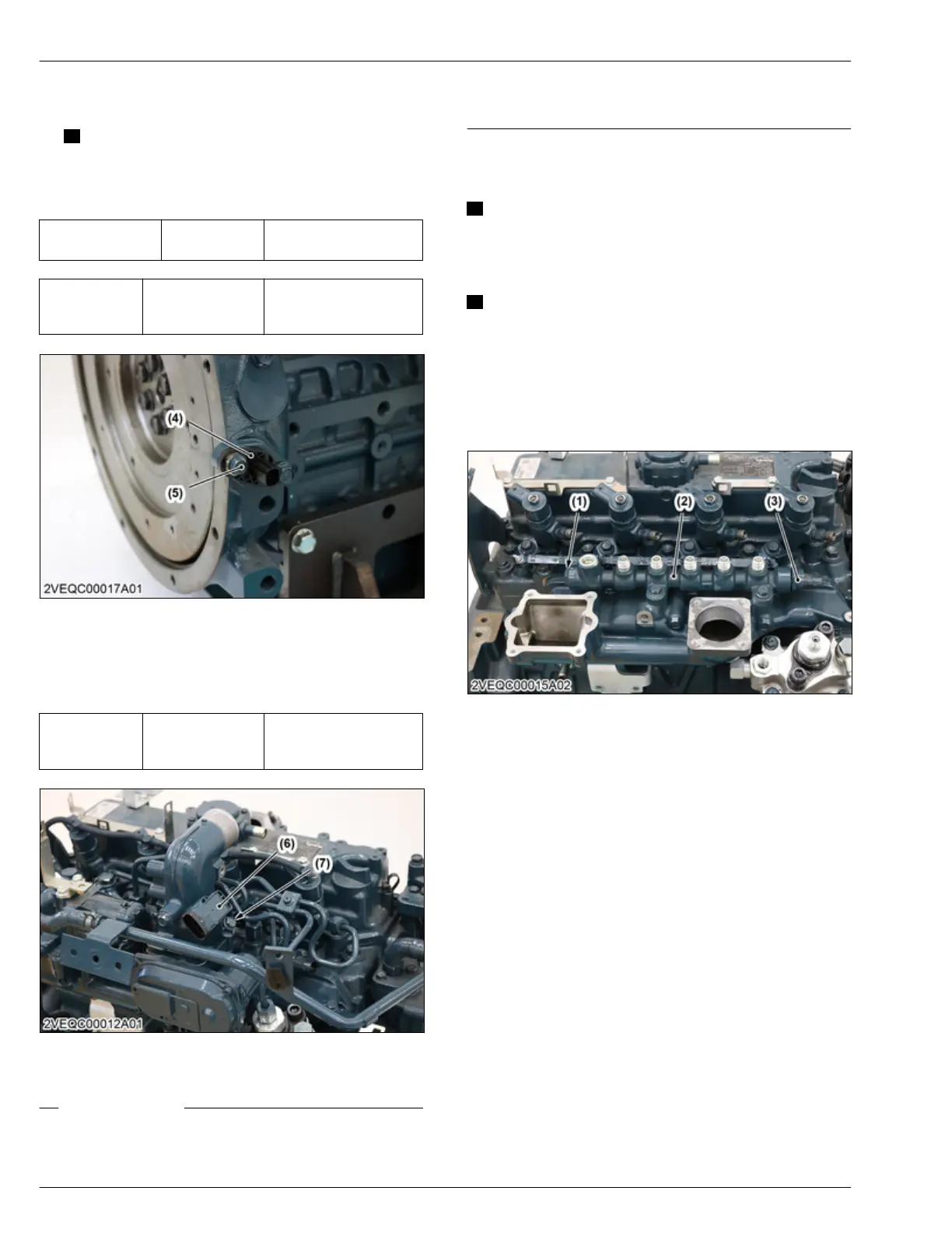
(4) Crankshaft position sensor (5) Crankshaft position sensor
mounting screw
6. Install the boost pressure sensor (6).
7. Tighten
the boost pressure sensor mounting screw
(7) to the specified torque.
Tightening tor-
que
Boost pressure
sensor mounting
screw (7)
9.81 to 11.3 N⋅m
1.00 to 1.15 kgf⋅m
7.24 to 8.33 lbf⋅ft
(6) Boost pressure sensor (7) Boost pressure sensor
mounting screw
RELATED PAGE
4.31 Adjusting air gap between crankshaft position
sensor and flywheel on page
4-114
4.32 Adjusting air gap between camshaft position
sensor and pulsar gear on page
4-115
6.34 Installing common rail
IMPORTANT
• Replace the
rail assembly, if the exchange of
the pressure limiter (1) or the rail pressure
sensor (3) is necessary.
NOTE
• Do not
remove the pressure limiter (1) and rail
pressure sensor (3) from the common rail (2).
• When installing the common rail (2), do not hold
it by the pressure limiter (1) and rail pressure
sensor (3).
1. Install the common rail (1).
(1) Pressure limiter
(2) Common rail
(3)
Rail pressure sensor
2. Connect the overflow pipe and hose (4).
3. Tighten
the overflow pipe joint screw to the
specified torque.
4. Install the injection pipes (5).
4. ENGINE
SERVICING
6. Assembling
D1803-CR-E4,D1803-CR-TE4,D1803-CR-TIE4,V2403-CR-E4,V2403-CR-TE4,V2403-CR-TE4BG,V2403-CR-TIE4
 Loading...


