3.19 Camshaft position sensor
3.19.1 Outline of camshaft position sensor
The camshaft position sensor senses the teeth on a
pulsar gear
and detects the angular position of the
camshaft.
3.19.2 Structure of camshaft position
sensor
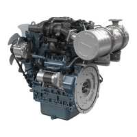
The camshaft position sensor is made up of a magnet
and connector and the like.
(1) Terminal 5 V
(2) Terminal signal
(3) Terminal ground
(4) G sensor input circuit
3.19.3 Function of camshaft position
sensor
The camshaft position sensor senses the teeth on a
pulsar
gear
and detects the angular position of the
camshaft.
The pulsar gear has teeth at non-equal intervals.
The engine ECU calculates the piston position based
on the signal detected.
The camshaft position sensor is a magnetic resistance
element type sensor.
When the pulsar gear passes by the sensor part, the
internal magnetic field changes.
AC voltage is generated by the change in magnetic
field and this is rectified and output to the engine ECU.
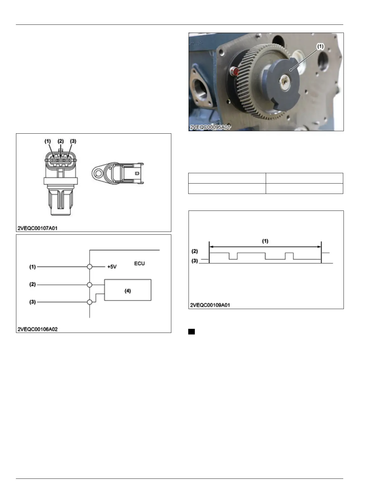
(1) Pulsar gear (cam)
3.19.4 Specification of camshaft position
sensor
Operating voltage 5 V
Pulsar gear number of teeth 3
Output waveform
(1) 3 pulses (6.28 rad 360°)
crank angle
(2) 5 V
(3) 0 V
NOTE
• Noted as G sensor on Diagmaster
4. ENGINE
MECHANISM
3. Fuel system
D1803-CR-E4,D1803-CR-TE4,D1803-CR-TIE4,V2403-CR-E4,V2403-CR-TE4,V2403-CR-TE4BG,V2403-CR-TIE4
 Loading...


