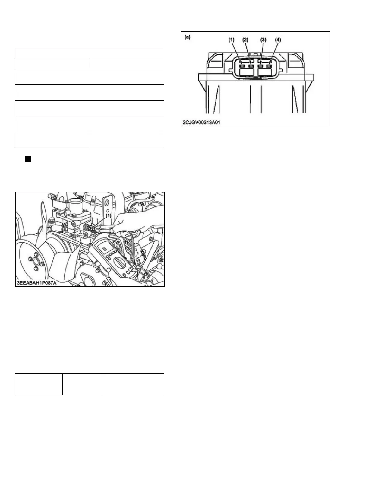
3. Measure
the
resistance between the terminals on
the sensor side.
Service specification
Temperature Resistance
20 ℃
68 ℉
Approx. 2.5 kΩ
40 ℃
104 ℉
Approx. 1.2 kΩ
60 ℃
140 ℉
Approx. 0.58 kΩ
80 ℃
176 ℉
Approx. 0.32 kΩ
100 ℃
212 ℉
Approx. 0.18 kΩ
NOTE
• If the
measurement is out of the service
specifications, replace the coolant
temperature sensor (1).
(1) Coolant temperature sensor
4.26 Checking EGR system
Tools required
• Circuit tester
1.
Disconnect the EGR valve connector.
2. Check of battery line of motor in EGR valve.
3.
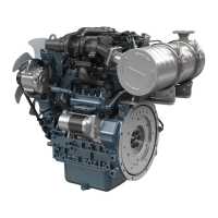
Measure the voltage between terminal power (4)
and terminal ground (3) at key ON status.
Terminal power (4)
and terminal
ground (3)
Service specifi-
cation
9 to 16 V
(1) Terminal CAN1-H
(2) T
erminal CAN1-L
(3) Terminal ground
(4) Terminal power (+12 V)
(a) Pin assignment
4.27 Checking air flow sensor
Tools required
• Circuit tester
1.
Turn the key switch OFF.
2. Remove the connector from the sensor side.
4. ENGINE
SER
VICING
4. Checking and adjusting
D1803-CR-E4,D1803-CR-TE4,D1803-CR-TIE4,V2403-CR-E4,V2403-CR-TE4,V2403-CR-TE4BG,V2403-CR-TIE4
 Loading...


