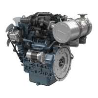
1. Remove
the
main bearing case mounting screw 2
(1).
(1) Main bearing case mounting
screw 2
2. Turn the crankshaft to set the crankpin of the third
cylinder to the bottom dead center
.
3. Pull out the crankshaft until the crankpin of the
second cylinder comes to the center of the third
cylinder.
4. Turn the crankshaft by 2.09 rad (120°)
counterclockwise to set the crankpin of the second
cylinder to the bottom dead center.
5. Pull out the crankshaft until the crankpin of the first
cylinder comes to the center of the third cylinder.
(a) Cut place to remove and in-
stall the crankshaft
6. Do the above steps again to pull out the crankshaft
completely.
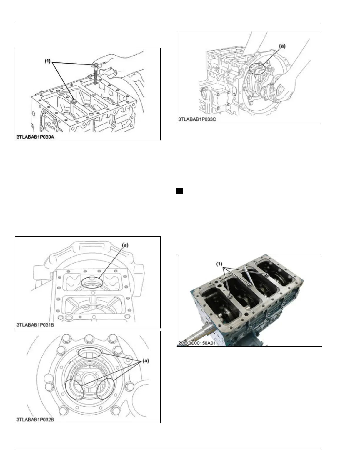
5.41 Removing crankshaft (for 4
cylinders)
NOTE
• Before you
disassemble, measure the side
clearance of crankshaft. Measure it when you
assemble again.
• This topic is used for only 4 cylinders engine
(V2403-CR-E4, -TE4, -TE4BG, -TIE4).
1. Remove the
main bearing case mounting screw 2
(1).
(1) Main bearing case mounting
screw 2
2. T
urn the crankshaft to set the crankpin of the fourth
cylinder to the horizontal directions (right or left).
3. Hold the crankpins to the horizontal directions (right
or left) and pull out the crankshaft completely.
4. ENGINE
SERVICING
5. Disassembling
D1803-CR-E4,D1803-CR-TE4,D1803-CR-TIE4,V2403-CR-E4,V2403-CR-TE4,V2403-CR-TE4BG,V2403-CR-TIE4
 Loading...


