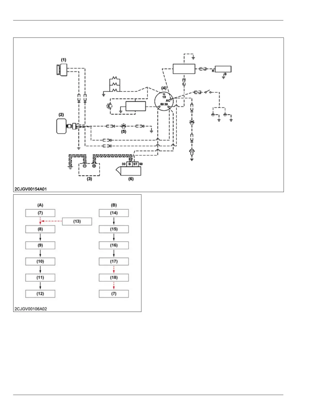
8.3 Flow of electrical system
(1) Alternator
(2) Regulator
(3)
Battery
(4) Key switch
(5) Charge lamp
(6) Starter
(7) Battery
(8) Starter
(9) Pinion gear
(10) Ring gear (flywheel)
(11) Crankshaft
(12) Start engine
(13) Key switch on the start posi-
tion
(14) Crankshaft
(15) Fan drive pulley
(16) Fan belt
(17) Alternator pulley
(18) Alternator
(A) Start flow
(B) Charge flow
Start flow
1.
When the key switch is rotated to the start position, current flows from the battery to the starter.
2.
Upon receiving current, the starter motor rotates and a pinion gear engages and starts to rotate.
3. The pinion gear that engages meshes with the ring gear (flywheel) and causes the flywheel to rotate.
4. The crankshaft that is connected to the flywheel rotates, initial combustion occurs in the engine and the engine
starts.
4. ENGINE
MECHANISM
8. Electrical system
D1803-CR-E4,D1803-CR-TE4,D1803-CR-TIE4,V2403-CR-E4,V2403-CR-TE4,V2403-CR-TE4BG,V2403-CR-TIE4
 Loading...