4.13 Checking magnetic switch
continuity
CAUTION
• To
prevent an accidental short circuit, attach
the positive cable to the positive terminal before
the negative cable is attached to the negative
terminal.
• Do not remove the battery cap while the engine
operates.
• Keep electrolyte away from eyes, hands and
clothes.
If you are spattered with it, clean with water
immediately.
• Keep open sparks and flames away from the
battery at all times.
Hydrogen gas mixed with oxygen becomes very
explosive.
Tools required
• Circuit tester
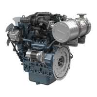
1. Push in the plunger.
2. Check the
continuity across the C terminal (1) and
the B terminal (2) with a circuit tester.
NOTE
• If it
is not continuous or it shows a value,
replace the magnetic switch.
Resistance be-
tween the C termi-
nal (1) and the B
terminal (2)
Service specifi-
cation
0 Ω
(1) C terminal (2) B terminal
4.14 Checking alternator on unit
CAUTION
• To
prevent an accidental short circuit, attach
the positive cable to the positive terminal before
the negative cable is attached to the negative
terminal.
• Do
not
remove the battery cap while the engine
operates.
• Keep electrolyte away from eyes, hands and
clothes.
If you are spattered with it, clean with water
immediately.
• Keep open sparks and flames away from the
battery at all times.
Hydrogen gas mixed with oxygen becomes very
explosive.
NOTE
• Before check
alternator on unit, do a check of
the below list.
– Battery terminal connections
– Circuit connection
– Fan belt tension
– Charge indicator lamp
– Fuses on the circuit
– Abnormal noise from the alternator
– Prepare full charged battery for the test.
• Do not touch the engine parts that turns while
the engine operates.
• Keep a safety distance from the engine parts
that turn.
Tools required
• Circuit tester
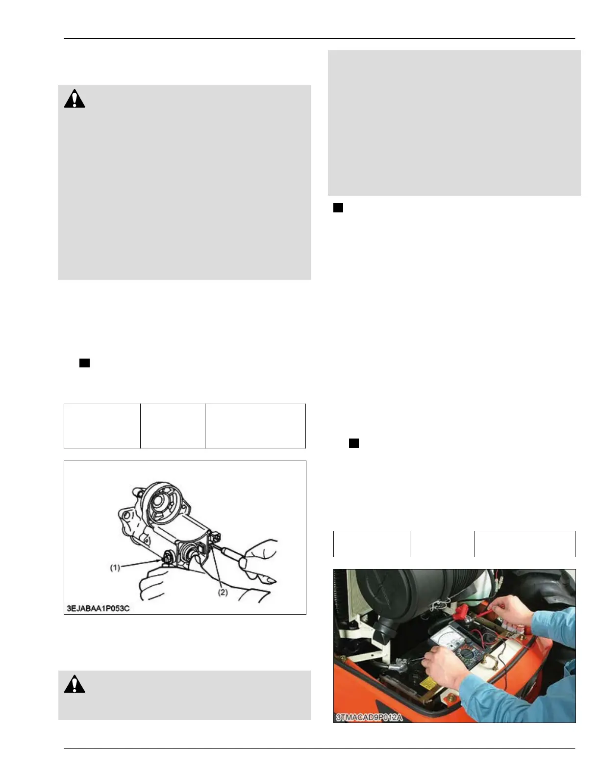
1. Start the engine.
2. Measure the voltage between battery terminals.
NOTE
• If the
results of alternator-on unit test are
not in the service specifications,
disassemble the alternator and check each
component part to find out the problem.
• Refer to the alternator section about
Disassembling, Assembling and Servicing.
Regulating voltage
at no load
Service specifi-
cation
13.8 to 14.8 V
(at 25 ℃ (77 ℉))
SERVICING
4. Checking and adjusting 4. ENGINE
D1803-CR-E4,D1803-CR-TE4,D1803-CR-TIE4,V2403-CR-E4,V2403-CR-TE4,V2403-CR-TE4BG,V2403-CR-TIE4
 Loading...


