4.21 Checking rail pressure sensor
Tools required
• Diagnosis tool
1.
Place the key switch in the ON position.
2. Check the "Actual rail pressure" and "Rail pressure
sensor output voltage" on the diagnosis tool data
monitor.
3. Start the engine.
4. Change the depressed amount of the accelerator
pedal, and check the same items again.
Engine state
Actual rail
pressure
Output volt-
age
Service speci-
fication
Key switch is
ON
Approx.
0 MPa
0 kgf/cm
2
0 psi
Approx. 0.3 V
After engine
start-up
Approx.
25.0 to
150 MPa
255 to
1520 kgf/cm
2
3630 to
21700 psi
Approx. 0.7 to
2.5 V
4.22 Checking boost pressure
sensor
Tools required
• Circuit tester
1.
Place the key switch in the ON position.
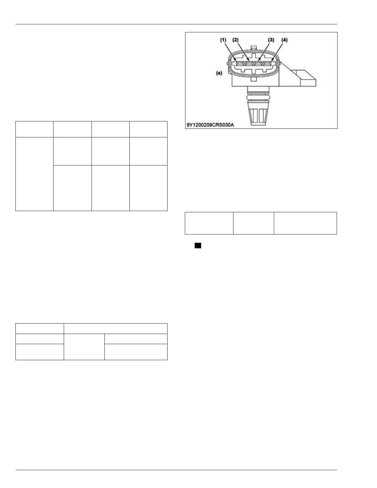
2. Measure the voltage between the boost pressure
sensor terminal (1) and (4) connector from the
wiring harness side.
3. Start the engine, change the depressed amount of
the accelerator pedal, and check the same items
again.
Engine state Output voltage
Key switch ON
Service specifi-
cation
Approx. 1.0 V
After engine start-
up
Approx. 1.0 to 2.2 V
(1) Terminal pressure signal
(2) T
erminal 5V
(3) Terminal temperature signal
(4) Terminal ground
(a) Pin assginment
4. Set the key switch to the OFF position.
5. Disconnect the
boost pressure sensor connector
from the socket.
6. Place the key switch in the ON position.
7. Measure the voltage between boost pressure
sensor terminal (2) and (4) connector (from the
wiring harness side).
Terminal 5V (2)
and terminal
ground (3)
Service specifi-
cation
Approx. 5 V
NOTE
• If the
measurement is out of the service
specification, replace the boost pressure
sensor.
4. ENGINE
SERVICING
4. Checking and adjusting
D1803-CR-E4,D1803-CR-TE4,D1803-CR-TIE4,V2403-CR-E4,V2403-CR-TE4,V2403-CR-TE4BG,V2403-CR-TIE4
 Loading...