5. Check
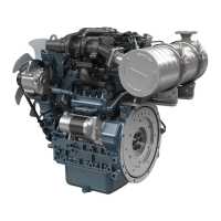
the subsequent valve clearance (5) at the
mark
[1TC] with a feeler gauge.
NOTE
• If the
clearance is out of the service
specifications, adjust with the adjusting
screw (3).
• Tighten the lock nut (4) of the adjusting
screw.
Valve clearance
(Cold)
Service specifi-
cation
0.18 to 0.22 mm
0.0071 to 0.0086 in.
Adjustable cylinder loca-
tion of piston
Valve arrangement
3 cylinder 4 cylinder
Intake
Ex-
haust
Intake
Ex-
haust
When No. 1 pis-
ton is at
compression top
dead center.
1 ☆
☆ ☆ ☆
2 ☆ ☆
3 ☆ ☆
4 - -
When No. 1 pis-
ton is at overlap
position.
1
2 ☆ ☆
3 ☆ ☆
4 - - ☆ ☆
(3) Adjusting screw
(4) Lock nut
(5)
Valve clearance
6. Install the removed parts.
Tightening tor-
que
Cylinder head cov-
er screw
6.86 to 11.3 N⋅m
0.700 to 1.15 kgf⋅m
5.06 to 8.33 lbf⋅ft
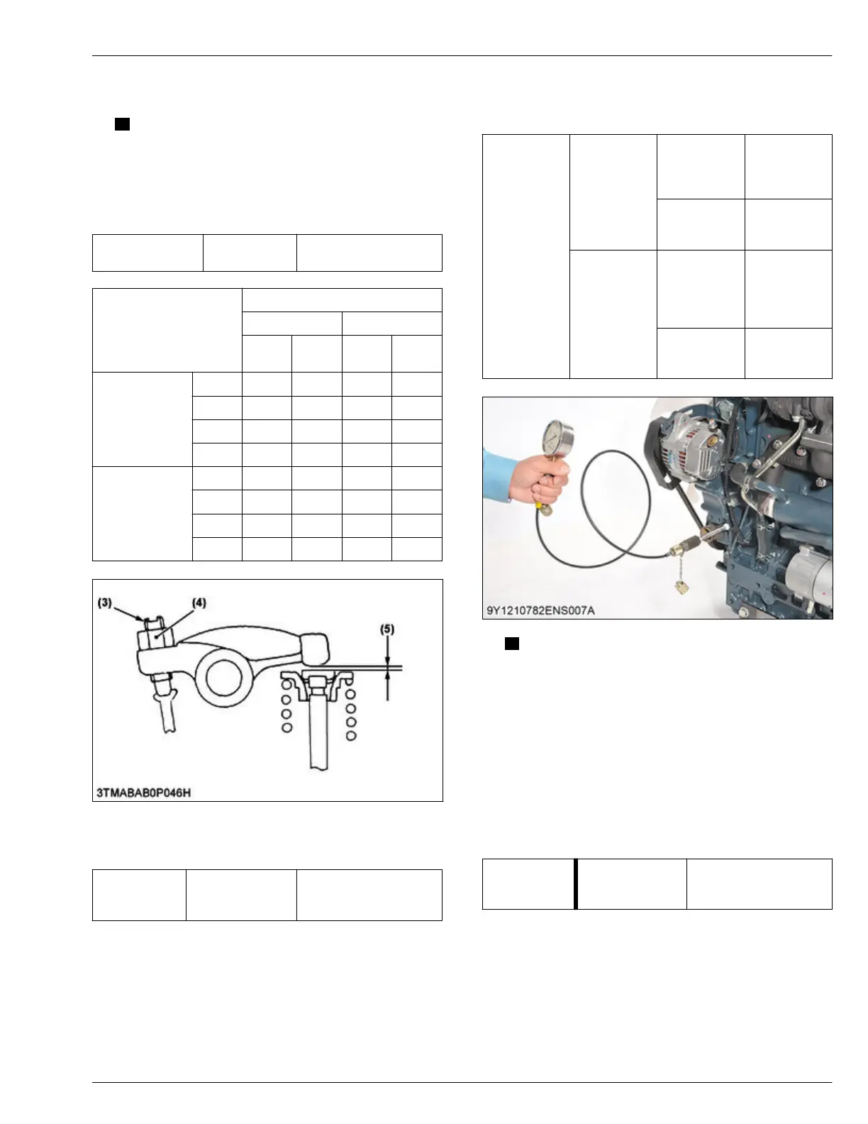
4.3 Checking engine oil pressure
Tools required
• Oil pressure tester
1.
Remove the engine oil pressure switch.
2. Set the oil pressure tester.
3. Operate the engine for warming-up.
4. Measure the
oil pressure at the idle speed and
rated speed.
Engine oil
pressure
At idle speed
Service speci-
fication
More than
98 kPa
1.0 kgf/cm
2
14 psi
Service limit
50 kPa
0.5 kgf/cm
2
7 psi
At rated
speed
Service speci-
fication
300 to
450 kPa
3.0 to
4.5 kgf/cm
2
43 to 64 psi
Service limit
250 kPa
2.5 kgf/cm
2
36 psi
NOTE
• If the
oil pressure is less than the service
limit, do a check below.
– Engine oil level
– Oil pump
– Oil strainer
– Oil filter cartridge
– Oil passage
– Oil clearance
– Relief valve
5. After checking the engine oil pressure, tighten its oil
pressure switch to the specified torque.
Tightening tor-
que
Oil pressure
switch
14.7 to 19.6 N⋅m
1.50 to 1.99 kgf⋅m
10.9 to 14.4 lbf⋅ft
SERVICING
4. Checking and adjusting 4. ENGINE
D1803-CR-E4,D1803-CR-TE4,D1803-CR-TIE4,V2403-CR-E4,V2403-CR-TE4,V2403-CR-TE4BG,V2403-CR-TIE4
 Loading...