2FB/2FC
1-6-15
Yes
No
Start
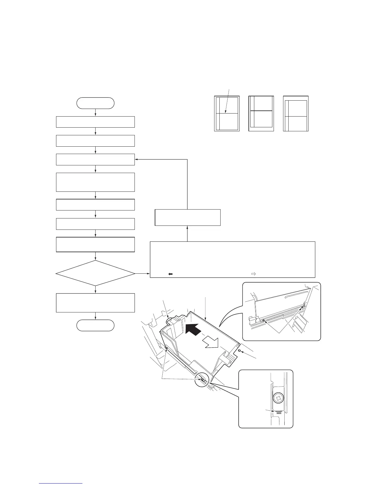
Enter maintenance mode.
Enter 034 using the numeric keys.
Press the start key.
Press the interrupt key.
Press the start key to output a test
pattern.
Is the image correct?
Press the stop/clear key to exit
maintenance mode.
End
Select LSUOUT
on the touch panel.
Loosen five screws securing
cassette 1 or 2 and adjust
the position.
For output example 1, move cassette
1 or 2 in the direction of black
arrow ( ).
Tighten five screws securing
cassette 1 or 2.
Select cassette 1 or 2.
For output example 2, move cassette
1 or 2 in the direction of white
arrow ( ).
(4) Adjusting the center line for cassette 1 or 2
Perform the following adjustment if there is a regular error between the center lines of the copy image and original when
the paper is fed from cassette 1 or 2.
Caution
After performing the following adjustment, adjust the position of the damper (see page 1-6-16).
Procedure
Figure 1-6-31
Figure 1-6-32
Center line of printing
Correct image Output
example 1
Output
example 2
Screws
Graduation
Screws
Cassette1 or 2
Screw
 Loading...