2FB/2FC-2.0
2-2-1
2-2 Electrical Parts Layout
2-2-1 Electrical parts layout
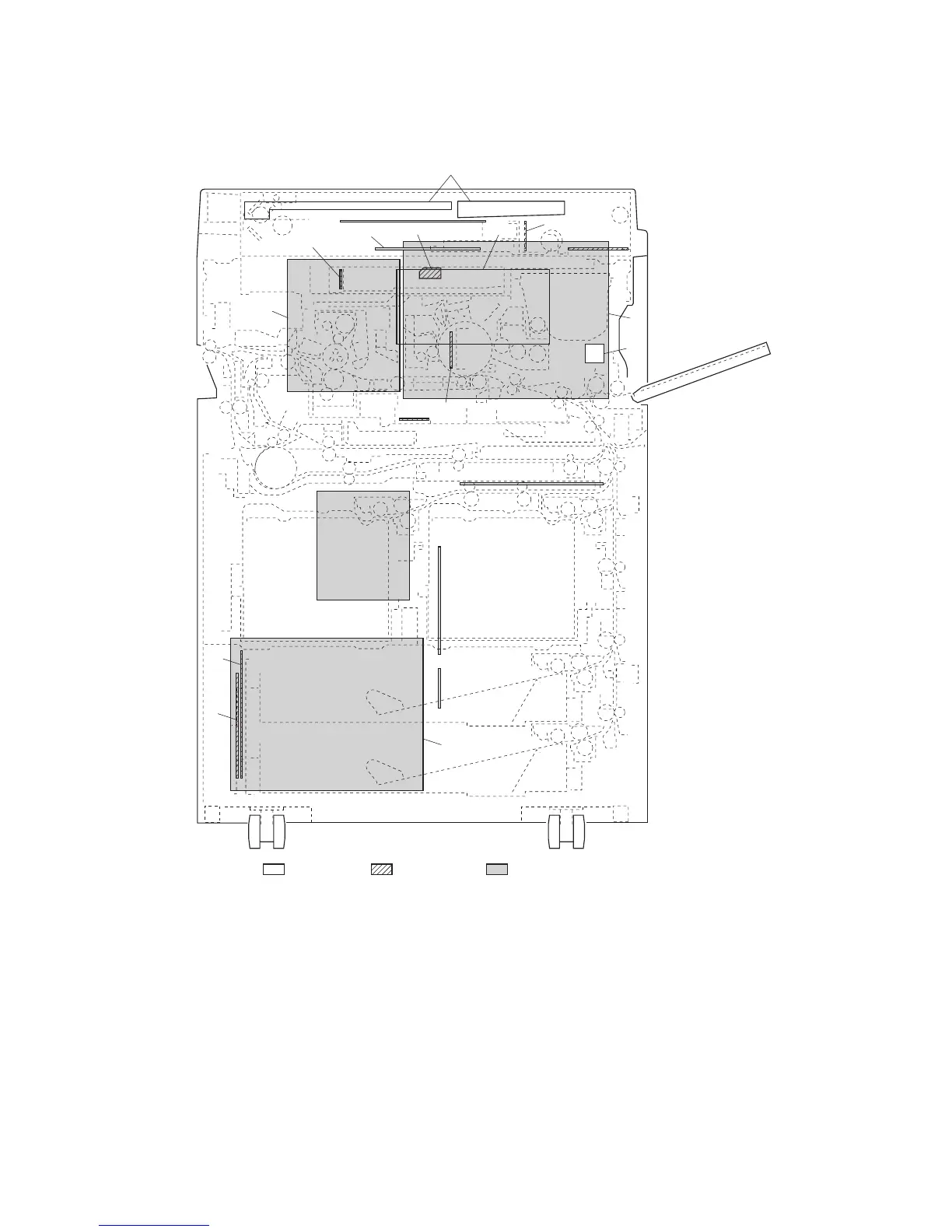
(1) PWBs
Figure 2-2-1 PWBs
1. Engine PWB (EPWB)................................... Controls the other PWBs, electrical components and optional devices.
2. Main PWB (MPWB) ..................................... Controls the image processing, operation panel and laser scanner unit.
3. AC power source PWB (ACPSPWB)........... Controls fuser heater M, S, and L. Distributes AC power source.
4. DC power source PWB (DCPSPWB) .......... Generates 24 V DC, 12 V DC, 8 V DC and 5 V DC.
5. Zener PWB (ZPWB)..................................... Controls the PTC (charging) voltage.
6. Operation PWB(OPWB)............................... Controls operation panel and LCD indication.
7. Scanner PWB (SPWB) ................................ Controls the scanner section.
8. SHD PWB (SHDPWB)................................. Controls the shading correction and AGC of CCD.
9. CCD PWB (CCDPWB)................................. Reads the image of originals.
10. Inverter PWB (INPWB) ................................ Controls the exposure lamp.
7
12
13
11
10
9
6
2
5
17
18
8
1
15
16
14
4
19
3
Machine front Machine inside Machine rear
20
 Loading...