WIRING DIAGRAMS
Page 2D-6 90-828631R3 MARCH 1999
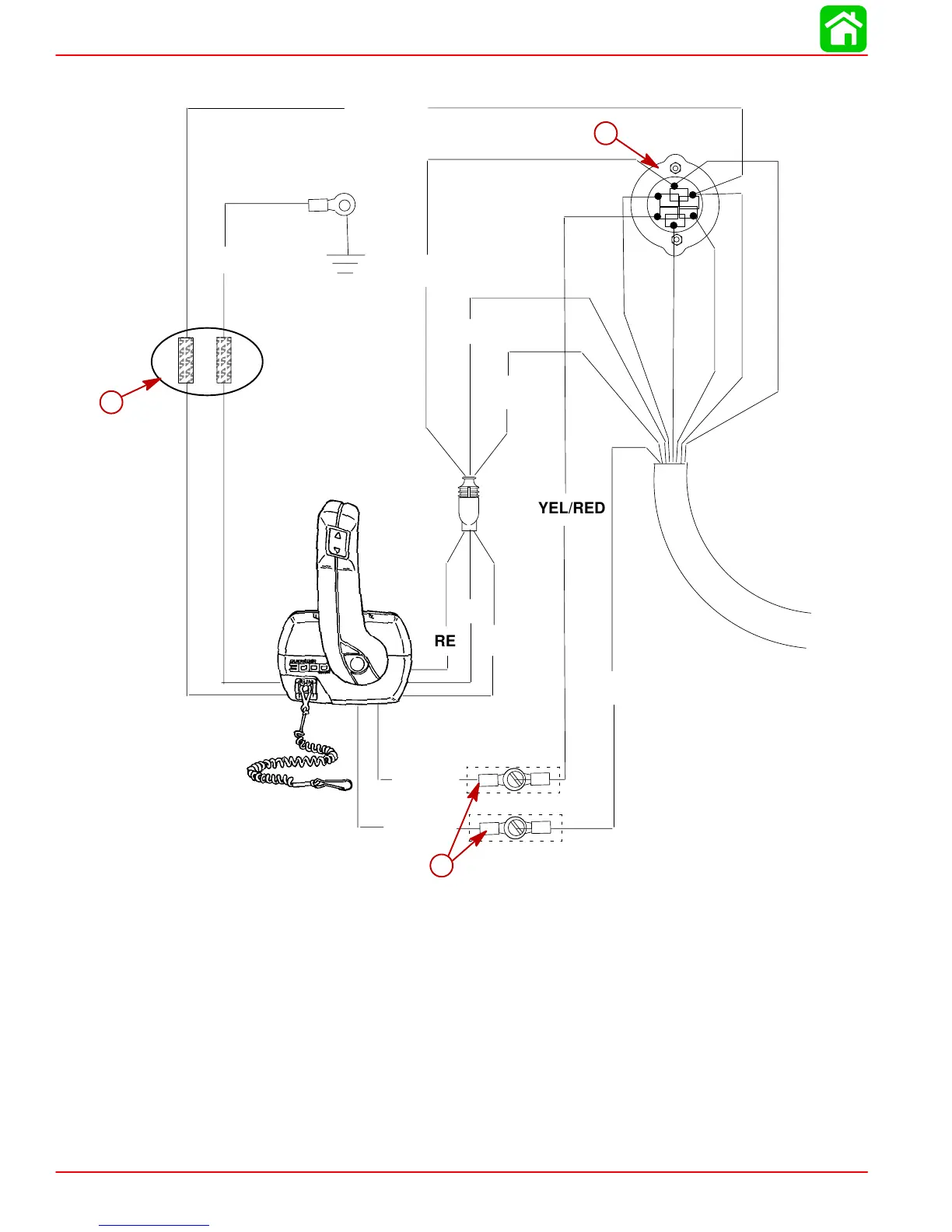
Commander 3000 Panel Mount Control
B
A
C
S
M
M
YEL/RED
RED
YEL/RED
YEL/RED
YEL/RED
PUR
GRN
BLU/WHT
GRN/WHT
RED
BLK/YEL
BLK
a
b
c
BLK = Black
BLU = Blue
BRN = Brown
GRN = Green
GRY = Gray
PUR = Purple
RED = Red
TAN = Tan
WHT = White
YEL = Yellow
a-Lanyard stop switch leads must be soldered and covered with shrink tube for a water proof connection.
If alternate method of connection is made, (use of electrical butt connector) verify connection is secure
and sealed for moisture proof connection.
b-Connect wires together with screw and hex nut (2 places); apply Quicksilver Liquid Neoprene to con-
nections and slide heat shrink tubing over each connection.
c-Keyswitch

 Loading...