CHARGING AND STARTING SYSTEM
90-828631R3 MARCH 1999 Page 2B-9
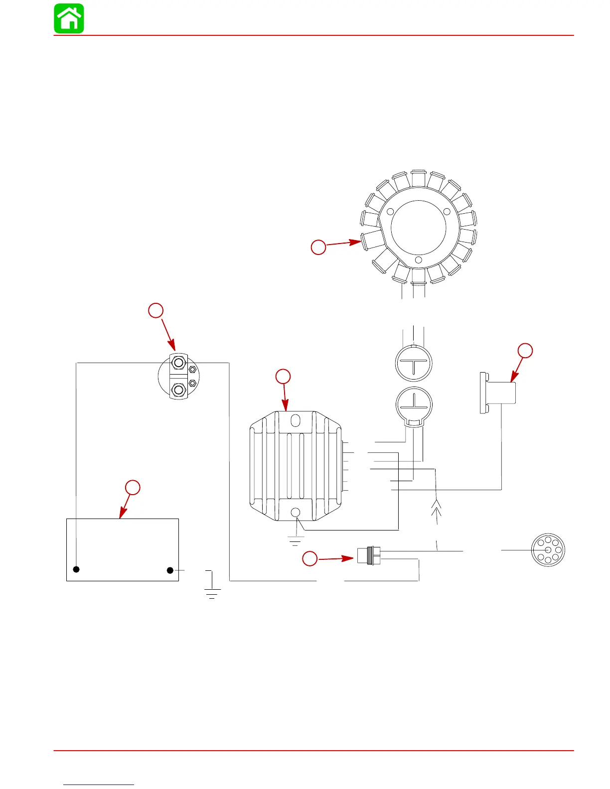
Battery Charging System
Description (10 Ampere)
The battery charging system components are the stator lighting coils, rectifier/regulator and
battery. Alternating current (generated in stator lighting coils) flows to the rectifier/regulator,
which changes the alternating current to a regulated direct current for charging the battery.
Wiring Diagram (10 Ampere)
12
3
12
3
BLK
AB
+
–
1
2
3
4
5
6
7
8
GRN
GRN
GRN
GRN
GRN/WHT
BLK
RED
GRN
GRN/WHT
RED/PPL
RED/PPL
RED
1–GRN
2–GRN
3–GRN/WHT
1–GRN
2–GRN
3–GRN
Blk
e
a
b
Blk = Black
Blu = Blue
Brn = Brown
Gry = Gray
Grn = Green
Orn = Orange
Pnk = Pink
Pur = Purple
Red = Red
Tan = Tan
Wht = White
Yel = Yellow
f
c
d
a-Stator
b-20 Ampere Fuse
c-Rectifier/Regulator
d-Battery
e-Starter Solenoid
f-Auto Starter

 Loading...