IGNITION
90-828631R3 MARCH 1999 Page 2A-9
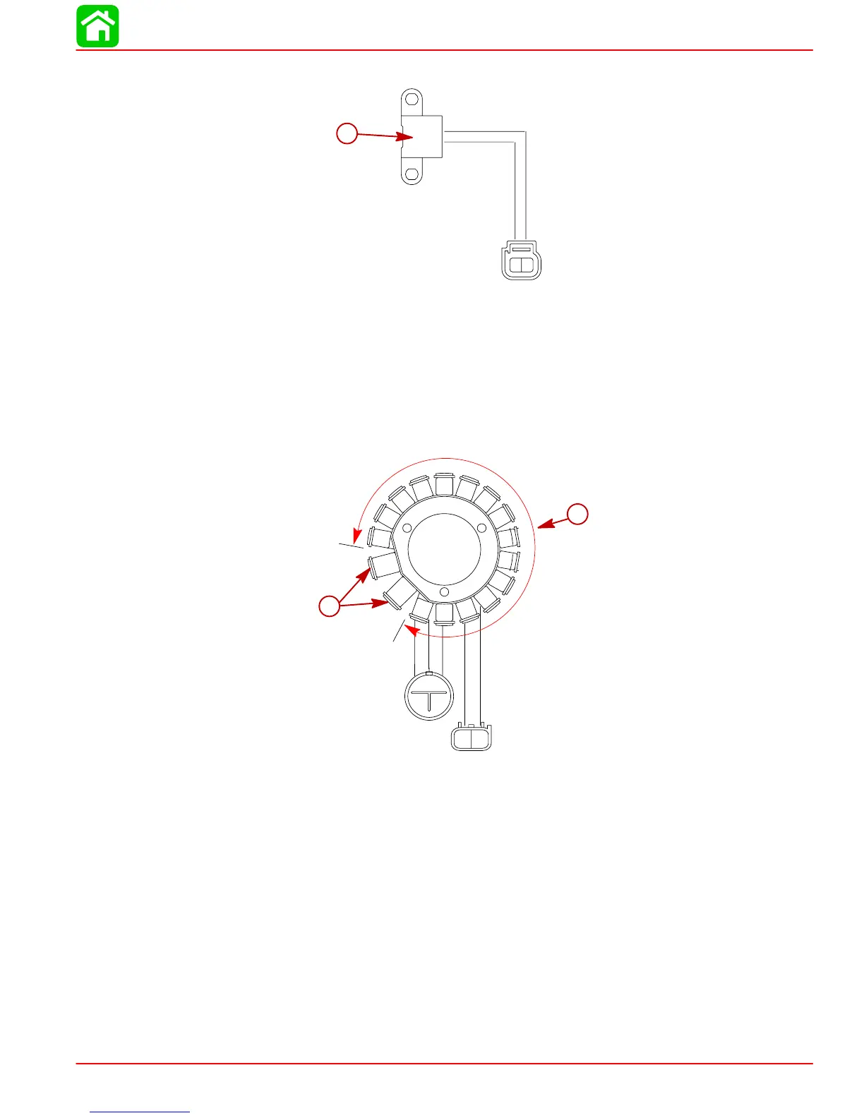
Trigger Coil
12
a
a-Trigger Coil
A single wound coil with magnet core mounted to one side of the stator mounting base. The
trigger is positioned on the outside of the flywheel assembly and is charged when a raised
boss on the flywheel passes the trigger/magnet winding. A pulse voltage is then sent to an
(SCR) switch within the CDI unit. The trigger is mounted in a fixed timing position.
Stator Assembly
12
3
12
a
b
a-Ignition Charge Coil
b-Lighting System Coils and Electrothermal Valve Coils
The stator assembly located under the flywheel contains the Ignition Charge Coils, and light-
ing system Coils. All of these coils make up the stator assembly.
As the flywheel permanent magnets pass the respective stator coil windings, an AC pulse
current is produced at each coil winding when magnet polarity changes. (South to North),
(North to South) etc.

 Loading...