3C-10 - FUEL SYSTEM 90-830234R3 DECEMBER 1997
Low Oil Sensor Test
NOTE: Low oil sensor is located in bottom of oil tank.
1. 1997 and Prior Models – Disconnect low oil sen-
sor leads (BLUE) between oil tank and warning
module.
1998 Models – Disconnect low oil sensor leads
(Light/Blue) from Tan/Blue and Black leads.
2. Using an ohmmeter, perform both tests in chart,
following.
Oil Level in
Oil Tank
Test Leads
Between
Scale Reading
(x__________)
1/2 Full to Full
Low Oil Sensor Leads
(BLUE)
No Continuity*
(R x 1)
Empty
Low Oil Sensor Leads
(BLUE)
Continuity**
(R x 1)
* If continuity is indicated, check to see if float (located inside
oil tank) is stuck in place or if magnet (attached to bottom
of float) has come loose. If float checks O.K., replace sen-
sor.
** If continuity is NOT indicated, check to see if float (located
inside oil tank) is stuck in place. If float is NOT stuck in
place, replace sensor (bottom of oil tank – remove screw
and retract sensor).
Warning Horn System
DESCRIPTION
Major components of the warning horn system are an
ignition switch, warning horn, low oil sensor, power-
head and temperature sensor.
With the ignition switch in the “Run” position, electri-
cal current is routed thru the warning horn and sup-
plied to the powerhead temperature sensor and low
oil sensor. If the powerhead overheats or the oil level
in the oil tank drops below approximately 1 quart (.95
liter), the electrical circuit is completed and the warn-
ing horn will sound.
Low Oil Condition – Indicated by an INTERMIT-
TANT BEEPING sound.
Overheat Condition – Indicated by a CONTINU-
OUS BEEPING sound.
WARNING HORN SYSTEM CHECK
1. Turn ignition key switch to “Run” position.
2. Warning horn will BEEP once.
3. Turn key switch to “Off” position.
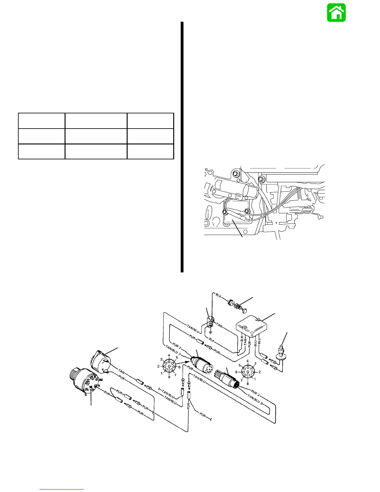
25939
a
a - Warning Module
51551
a
b
c
d
e
f
g
h
a - Powerhead Temperature Sensor
b - Warning Module
c - Terminal Block
d - Warning Horn
e - Ignition Switch
f - Engine Harness
g - Remote Control Harness
h - Low Oil Sensor
 Loading...