7A-2 - ATTACHMENTS/CONTROL LINKAGE 90-830234R3 DECEMBER 1997
CAUTION
Steering link must be installed in rear hole in
engine steering arm. Failure to install in rear hole
may cause damage to steering system.
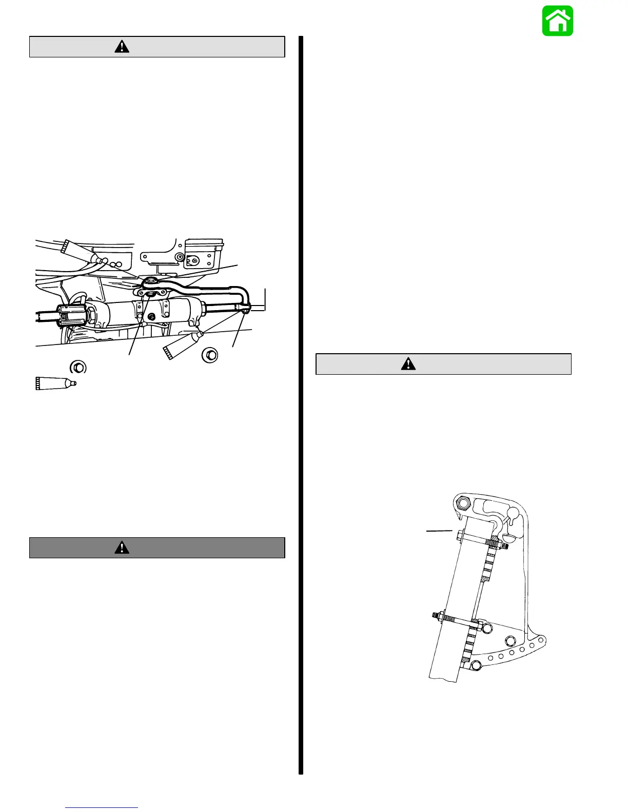
5. Lubricate hole in end of steering cable with
Quicksilver 2-4-C w/Teflon and assemble steer-
ing link rod to steering cable with 2 flat washers
and locknut as shown. Torque locknut to 120 lbs.
in. (13.5 Nm) maximum and back off 1/4-turn.
6. Lubricate ball joint in steering link rod with 2-4-C
w/Teflon and assemble to rear hole in engine
steering arm with pivot bolt and locknut. Torque
pivot bolt, then locknut to 20 lbs. ft. (27.0 Nm).
d
a
c
b
95
2-4-C With Teflon (92-825407A12)
95
95
50099
a - Flat Washers (2)
b - Locknut
c - Pivot Bolt
d - Locknut
Ride-Guide Attachment –
Dual Front Installation
(92876A2)
WARNING
Quicksilver Super Ride-Guide Steering (Dual
Cables) must be used with this attaching kit. Fail-
ure to adhere to this requirement could result in
steering system failure.
Installation and Maintenance
IMPORTANT: The distance from each engine’s
centerline to the side of transom opening must
be a minimum of 16″ (40.6cm).
This kit contains all necessary parts to connect both
engines to Ride-Guide Steering cables for 22-1/2
(57.2cm) thru 24-1/2(62.2cm), refer to Figure 14,
page 7A-14 for additional extension couplers.
Cable Routing Types
Use “1” or “2”, following, to route steering cables:
1. Parallel cable routing: Cables routed together
down starboard side of boat. Refer to “Parallel
Routed Steering Cables and Attaching Kit Instal-
lation,” immediately following.
2. Opposite side cable routing: One cable routed
down starboard side of boat and one cable routed
down port side of boat. Refer to “Opposite Side
Routed Steering Cables and Attaching Kit Instal-
lation,” page 7A-8.
CAUTION
With this kit installed, the upper (engine) mount-
ing bolts must be installed so that hex head end
of bolts is on the inside of boat transom, as illus-
trated below. Failure to install upper mounting
bolts, as shown in illustration, could result in in-
terference between outer steering cable locking
sleeve and ends of mounting bolts when engine
is tilted up.
a
a - Install Upper Bolts so that Hex Head End of Bolts Are on
the Inside of Boat Transom
 Loading...