2A-22 - ELECTRICAL 90-830234R3 DECEMBER 1997
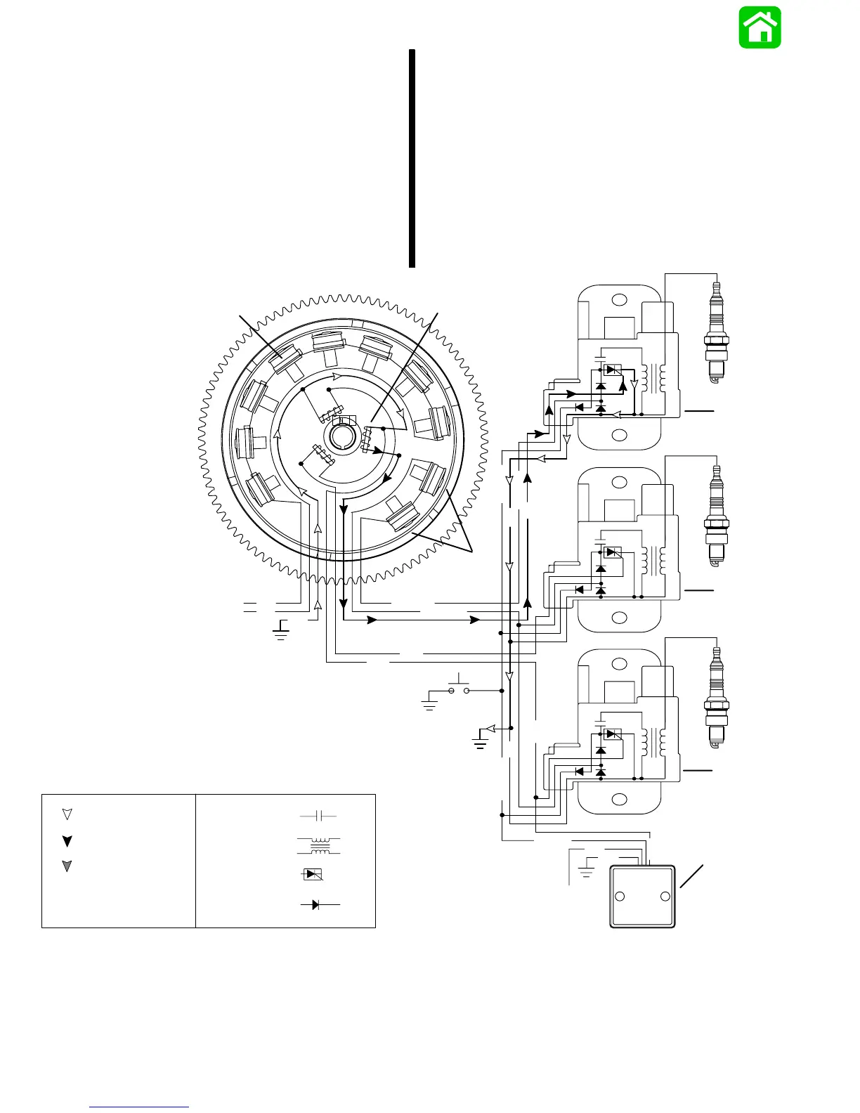
#1 Cylinder Trigger Circuit
The TRIGGER assembly (also mounted under the
flywheel) has one coil for each cylinder. These coils
are mounted adjacent to the flywheel center hub. The
center hub of the flywheel contains a permanent
magnet with two north-south transitions.
As the flywheel rotates, the magnet north-south tran-
sitions pass the trigger coils. This causes the trigger
coils to produce a voltage pulse which is sent to the
respective capacitor discharge module (CDM). A
positive voltage pulse (N-S) will activate the electron-
ic switch (SCR) inside the capacitor discharge mod-
ule (CDM). The switch discharges the capacitor volt-
age through the coil primary windings. The return
voltage pulse exits the CDM through the ground wire
and returns through the trigger ground.
NOTE: 4 cylinder models have 4 triggers.
N
BLK
N
S
S
S
S
S
S
N
N
N
N
N
S
GRN/WHT
WHT/GRN
YEL
YEL
BRN
BLK
WHT
+
+
+
_
_
_
WHT/GRN
PPL
BRN
BLK
BLK/YEL
BRN
BLK/YEL
BLK
BLK/YEL
2
3
PPL
a
b
c
d
e
f
g
h
i
j
1
Return Voltage
Source Voltage
SCR-
CAPACITOR-
COIL-
DIODE-
Trigger Voltage
a - Battery Charging Coils
b - Trigger Coils
c - Capacitor Charge Coils
d - CDM #1
e - CDM #2
f - CDM #3
g - Rev. Limiter (Not Used On All Models)
h - To Ignition Switch
i - Stop Switch
j - To Voltage Regulator
 Loading...