90-830234R3 DECEMBER 1997 ELECTRICAL - 2A-21
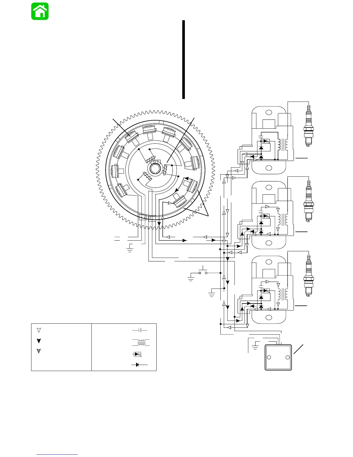
Capacitor Charging #2 & #3 CDM
The flywheel rotates the permanent magnets past
the capacitor charging coils causing the coils to pro-
duce AC voltage (260-320 volts). The opposite volt-
age pulse is then conducted to the CAPACITOR DIS-
CHARGE MODULES (CDM), where it is rectified
(DC) and stored in a capacitor. The stator voltage re-
turn path is through the ground wire of the other CDM
and back through that CDM’s charging coil wire to the
capacitor charging coils.
NOTE: #1 CDM stator voltage return path is through
either CDM #2 or #3. The return path for CDM #2 and
#3 is through CDM #1, if #1 stator wire is discon-
nected the engine will die (the stator circuit is incom-
plete and the capacitors cannot be charged).
N
BLK
N
S
S
S
S
S
S
N
N
N
N
N
S
GRN/WHT
WHT/GRN
YEL
YEL
BRN
BLK
WHT
+
+
+
_
_
_
WHT/GRN
PPL
BRN
BLK
BLK/YEL
BRN
BLK/YEL
BLK
BLK/YEL
2
3
PPL
a
b
c
d
e
f
g
h
i
j
1
Return Voltage
CAPACITOR-
Source Voltage
COIL-
SCR-
DIODE-
Trigger Voltage
a - Battery Charging Coils
b - Trigger Coils
c - Capacitor Charge Coils
d - CDM #1
e - CDM #2
f - CDM #3
g - Rev. Limiter (Not Used On All Models)
h - To Ignition Switch
i - Stop Switch
j - To Voltage Regulator
 Loading...