90-830234R3 DECEMBER 1997 MID-SECTION - 5C-45
Bleeding Power Trim Unit
1. Secure power trim unit in soft jawed vise.
2. Add power trim fluid until its even with the bottom
of the fill hole. Reinstall plug.
3. Close the manual release valve. (Turn full clock-
wise).
a
b
55263
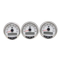
a - Reservoir Plug/Fill Hole
b - Manual Release Valve
4. Using a 12 volt power supply, connect the posi-
tive lead to (BLUE) trim motor wire and negative
lead to (GREEN) trim motor wire and drive shock
rod to the up position. Repeat for three times.
5. Connect the positive lead to the (GREEN) trim
motor wire, and the negative lead to the (BLUE)
trim motor wire and drive the shock rod to the
down position.
6. Recheck fluid level, add fluid if required and re-
peat cycle until fluid level stays even with the bot-
tom of the fill hole.
Installation of Power Trim
System
1. Lubricate lower pivot pin, mounting holes with
2-4-C w/Teflon Marine Lubricant.
2. Start lower pivot pin into pivot pin bore and posi-
tion lower dowel pin (Retained) in its respective
hole.
a
b
51148
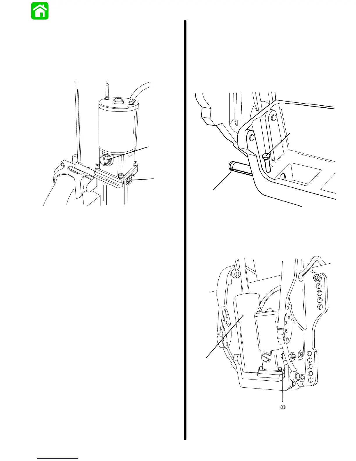
a - Lower Pivot Pin
b - Lower Dowel Pin
3. Position trim cylinder assembly (Bottom First)
between clamp brackets.
a
55467
a - Trim Cylinder Assembly
 Loading...