90-830234R3 DECEMBER 1997 POWERHEAD - 4-57
• Position clips, align cover holes and insert bolts -
finger tighten (located under bolts #2 and 10).
• Insert remaining cover bolts - finger tighten.
NOTE: Keep clips positioned, as shown, during
torque sequence.
CYLINDER HEAD COVER TORQUE SEQUENCE
All Cover Bolts: 18 lb. ft. (24.4 Nm)
3 Cylinder Models
15
11
6
1
3
7
9
13
19
17
18
12
8
4
2510
14
16
19
14106248
12
16
20
21
22
23
15117315913
17
18
4 Cylinder Models
23014
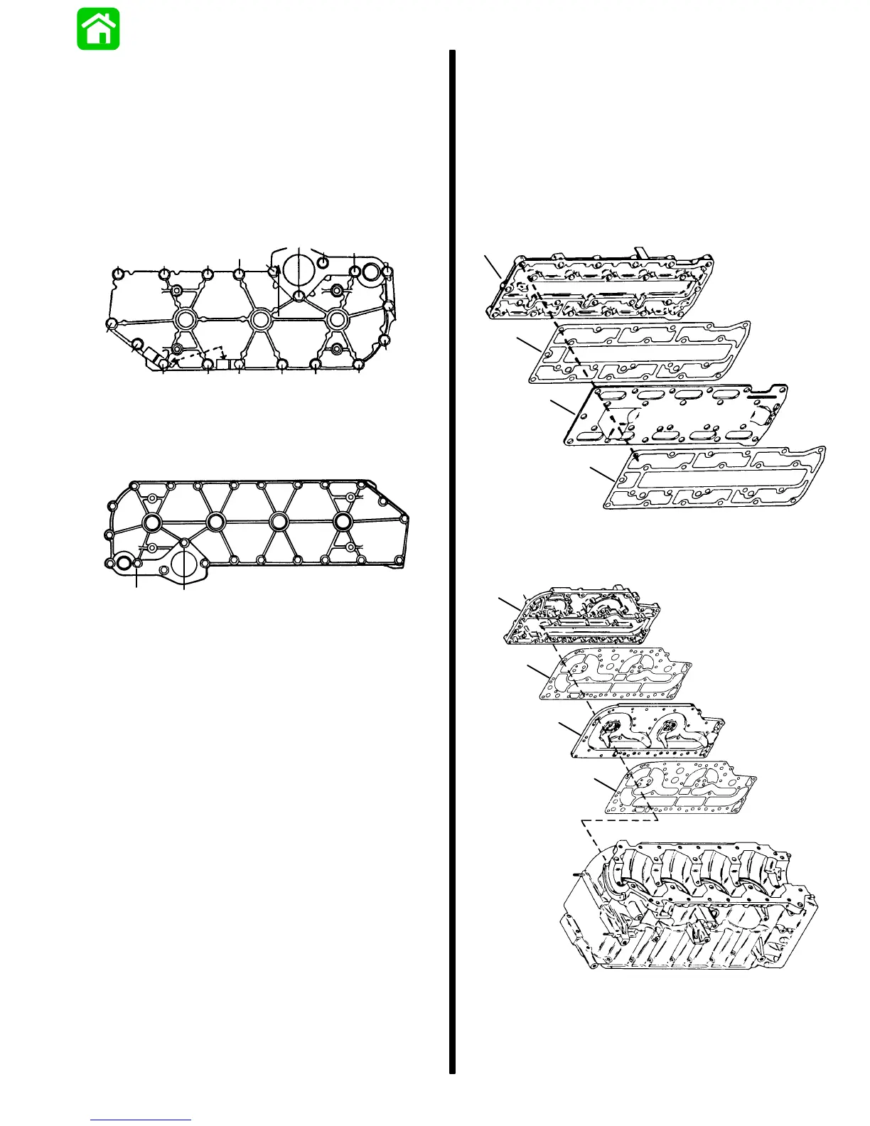
Exhaust Plate Cover and Exhaust
Divider Plate
• Assemble in order shown.
a. Exhaust Plate Gasket
b. Divider Plate
c. Exhaust Plate Gasket
d. Exhaust Plate Cover
3 Cylinder Models
4 Cylinder Models
a
b
c
d
a
b
c
d
51523
• Insert bolts (24) and finger tighten.
• Torque bolts in sequence.
 Loading...