5E-30 - MID-SECTION 90-830234R3 DECEMBER 1997
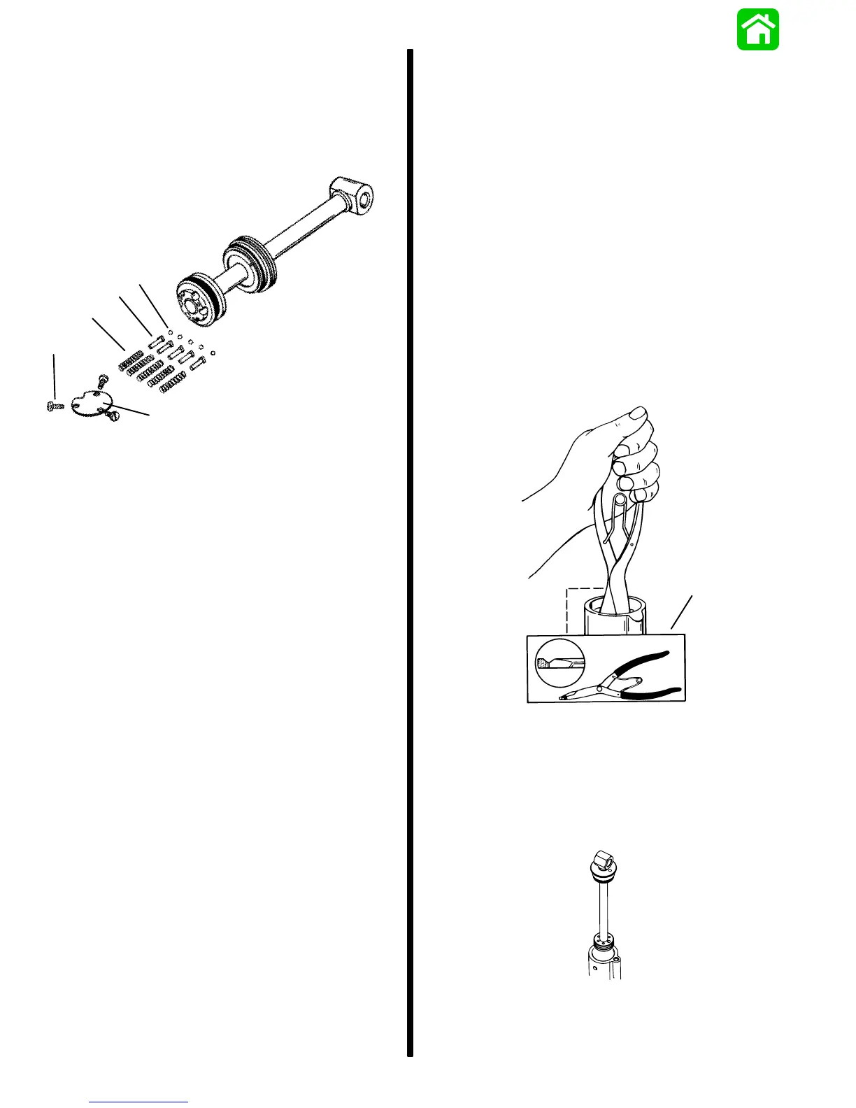
9. Install ball, seat, and spring (five sets) to shock
rod piston.
10. Secure components with plate. Torque screws to
35 lb. in. (4.0 N⋅m).
11. Remove shock rod assembly from vise.
a
c
d
e
b
51147
a - Screw (3) Torque to 35 lb. in. (4.0 N⋅m)
b - Plate
c - Spring (5)
d - Seat (5)
e - Ball (5)
Shock Rod Installation and Fluid
Filling Procedure
NOTE: There are two ways for the filling procedure.
The first is the easiest and less time consuming.
Filling Procedure Option One
1. Place trim cylinder in soft jawed vice.
2. With manifold cam lever closed (Up Position), fill
cylinder and manifold to top with Quicksilver
Power trim and steering fluid, or (ATF) automatic
transmission fluid. Let bubbles disperse.
3. Install lubricated O-ring to memory piston.
4. Using lock ring pliers (Craftsman P/N 4735) or
(Snap-on P/N SRP4) set memory piston in top of
cylinder then open cam lever (Down Position)
and push memory piston down just below cylin-
der treads. Close cam lever (Up Position).
a
51144
a - Lock Ring Pliers
5. Fill top of cylinder again with fluid to top and install
shock rod assembly on top memory piston. Open
cam lever (Down Position) and push shock rod
assembly down to 1/8″ (3.2mm) below cylinder
threads. Close cam lever (Up Position).
 Loading...