90-830234R3 DECEMBER 1997 ATTACHMENTS/CONTROL LINKAGE - 7B-21
Throttle Cable Installation
and Adjustment to Engine
IMPORTANT: Turn throttle cable conduit clock-
wise until bottomed on tiller handle then back off
one turn before reconnecting throttle cable to en-
gine.
1. Rotate throttle twist grip fully clockwise to stop
“IDLE” position.
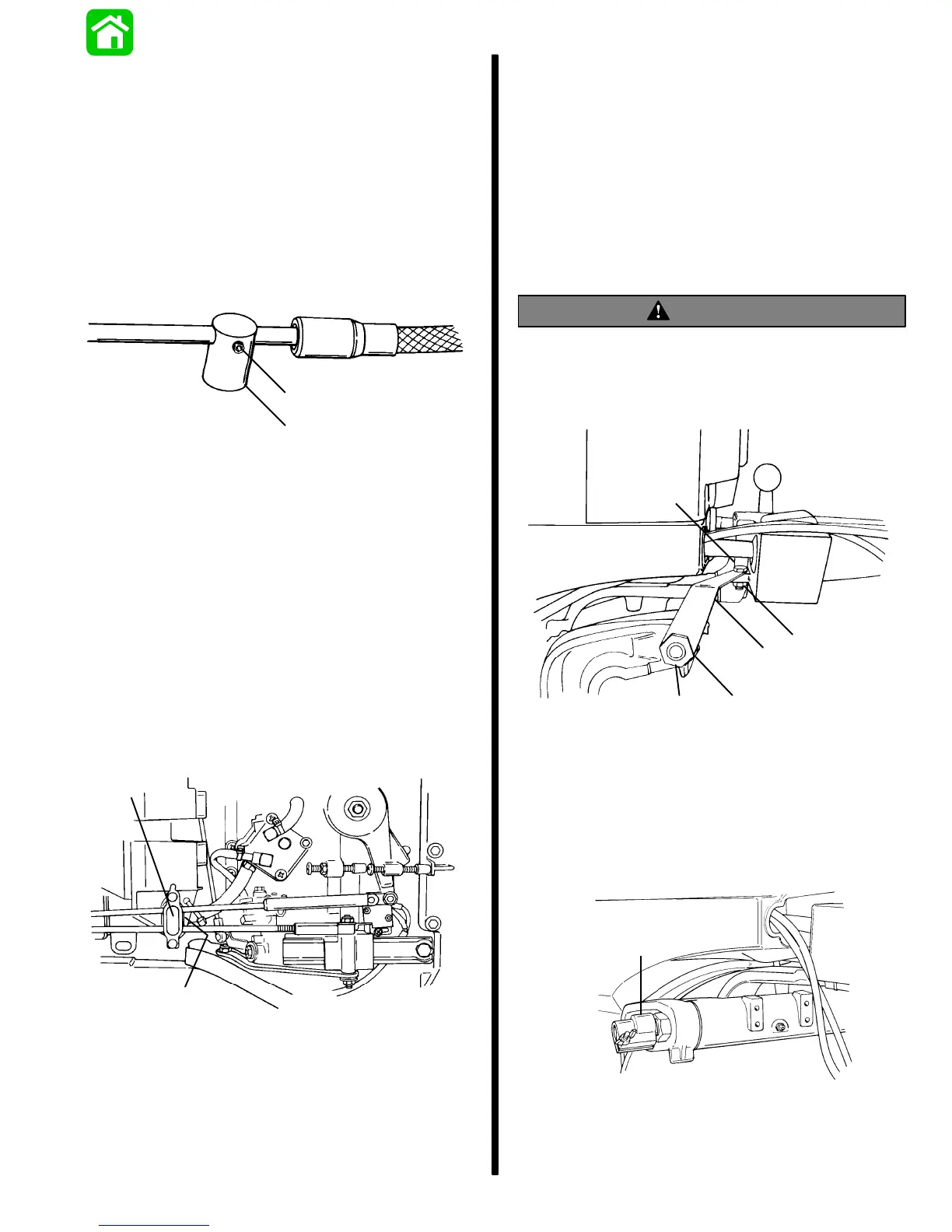
2. Back out set screw from throttle cable barrel until
2 or 3 threads of set screw are exposed.
a
b
51077
a - Set Screw
b - Throttle Cable Barrel
3. Place end of throttle cable guide over peg of
throttle lever and secure with locknut and washer.
Tighten until snug then back off 1/4 turn.
IMPORTANT: DO NOT exceed 1/4 turn on set
screw after it has bottomed-out.
4. Holding engine throttle lever against idle stop,
adjust throttle cable barrel to slip into upper hole
of barrel receptacle, with a very light preload of
throttle lever against idle stop. Apply small
amount of Loctite 271 to threads of allen screw
and tighten until snug, then an additional 1/8 turn.
Lock barrel in place with barrel retainer.
c
d
51620
c - Barrel Receptacle
d - Barrel Retainer
5. Check preload on throttle cable by placing a thin
piece of paper between idle stop screw and idle
stop. Preload is correct when paper can be re-
moved without tearing, but has some drag on it.
Readjust cable barrel, if necessary.
6. Reinstall outboard cowling.
7. Reconnect POSITIVE (+) and NEGATIVE (–)
cables to battery.
Co-Pilot Installation
WARNING
Co-Pilot Assembly (supplied) MUST BE installed
on tiller handle models.
1. Remove and discard shipping bracket compo-
nents, if installed.
a
b
c
d
e
51623
a - Bolt
b - Nut
c - Shipping Bracket
d - Washer
e - Nut
2. Thread friction device onto starboard end of tile
tube, until securely tightened and position wing
nut toward front of outboard as shown.
a
51624
a - Friction Device
3. Loosen wing nut on friction device and insert pilot
rod thru friction device and into tilt tube.
 Loading...