7A-12 - ATTACHMENTS/CONTROL LINKAGE 90-830234R3 DECEMBER 1997
Steering System Tension Adjustment
OPPOSITE SIDE ROUTED STEERING CABLES
IMPORTANT: After this Ride-Guide Attachment
Kit is installed, there must be proper tension in
the steering system. Not enough tension will
cause slack (play) in steering system. Too much
tension will cause steering cables to bind. Per-
form Step 1, following, to adjust for correct ten-
sion.
1. Loosen adjustment nuts and pull steering cable
mounting tube (by hand) away from end of steer-
ing cable (to remove slack in steering system).
Tighten adjustment nuts and check system for
slack (play) or too much tightness. If steering sys-
tem is too tight, readjust tube toward end of steer-
ing cable (Figure 10) or, if too much slack (play)
exists in system, readjust tube away from end of
steering cable (Figure 10). Tighten nuts and
readjust, if necessary.
a
c
d
b
51887
a - Steering Cable Mounting Tube
b - Adjustment Nuts
c - Adjust Tube in This Direction to Remove Slack from Steer-
ing System
d - Adjust Tube in This Direction to Reduce Tightness from
Steering System
Figure 10. Steering System Tension Adjustment
(Opposite Side Routed Steering Cables)
a
bb
51887
a - Adjust Nuts; Torque to 35 lbs. ft. (47.5 Nm)
b - Tab Lockwashers (Bend Against Flat on Each Nut.)
Figure 11. Adjustment Nuts Secured with Lock-
tabs
d
c
b
ae
51888
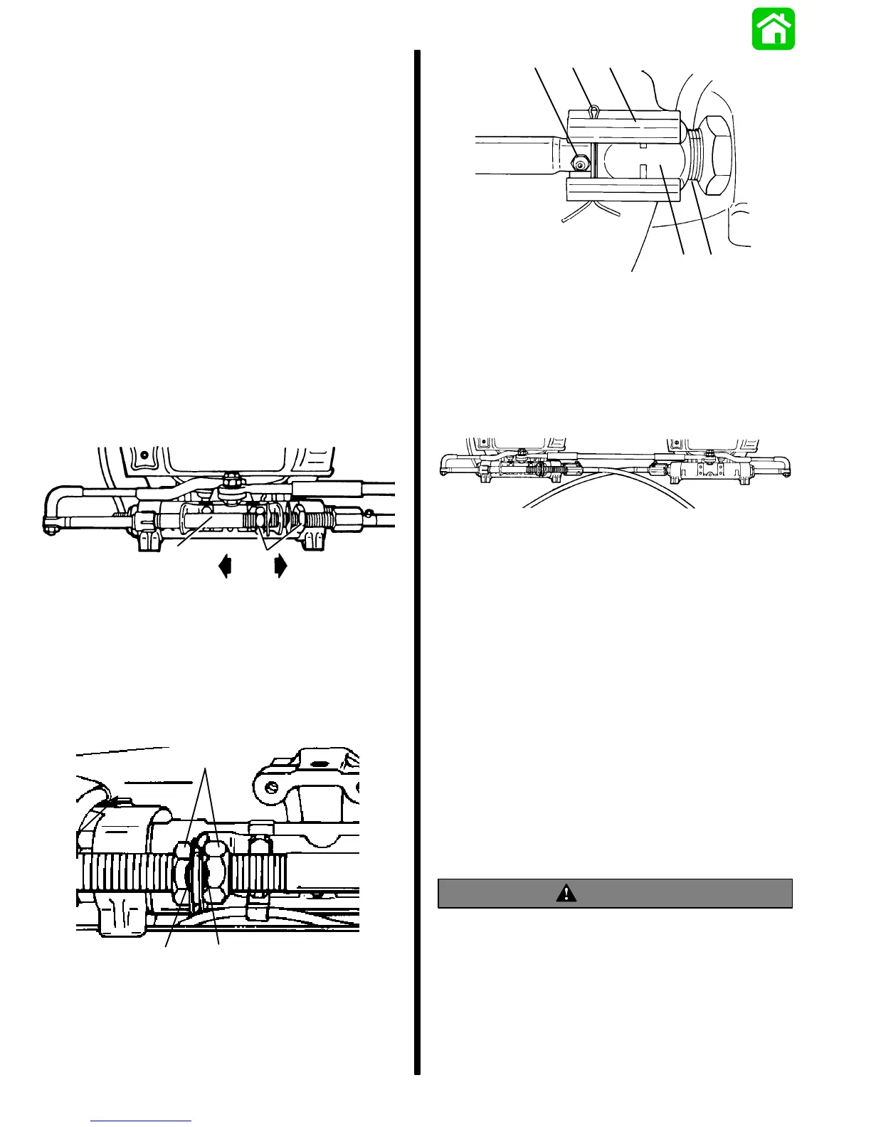
a - Steering Cable Attaching Nut;Torque to 35 lbs. in.
(47.5 Nm)
b - Locking Sleeve (Provided with Ride-Guide Steering
Cables)
c - Cotter Pin
d - Grease Fitting
e - Cable Guide Tube
Figure 12. Steering Cables Fastened to Tubes
50101
Figure 13. Attachment Kit Installation Complete
2. After steering system tension is adjusted correct-
ly, torque adjustment nuts (Figure 11) to 35 lbs.
ft. (47.5 Nm) and bend a tab lockwasher against
a flat on each nut.
3. Secure each steering cable attaching nut to
tubes by torquing steering cable attaching nuts
(Figure 12) to 35 lbs. ft. (47.5 Nm).
4. Install rubber bumpers on inside of locking
sleeves, then install a locking sleeve over each
steering cable attaching nut and secure with cot-
ter pin. Spread ends of cotter pin. Be sure to
install cotter pin so that it is located in-between at-
taching nut and grease fitting (Figure 12).
5. Install new trim tabs as outlined in “Trim Tab
Installation,” following.
WARNING
After installation is complete (and before operat-
ing engine), check that boat will turn right when
steering wheel is turned right and that boat will
turn left when steering wheel is turned left. Check
steering thru full range (left and right) at all tilt
angles to assure interference-free movement.
 Loading...