90-830234R3 DECEMBER 1997 ELECTRICAL - 2A-25
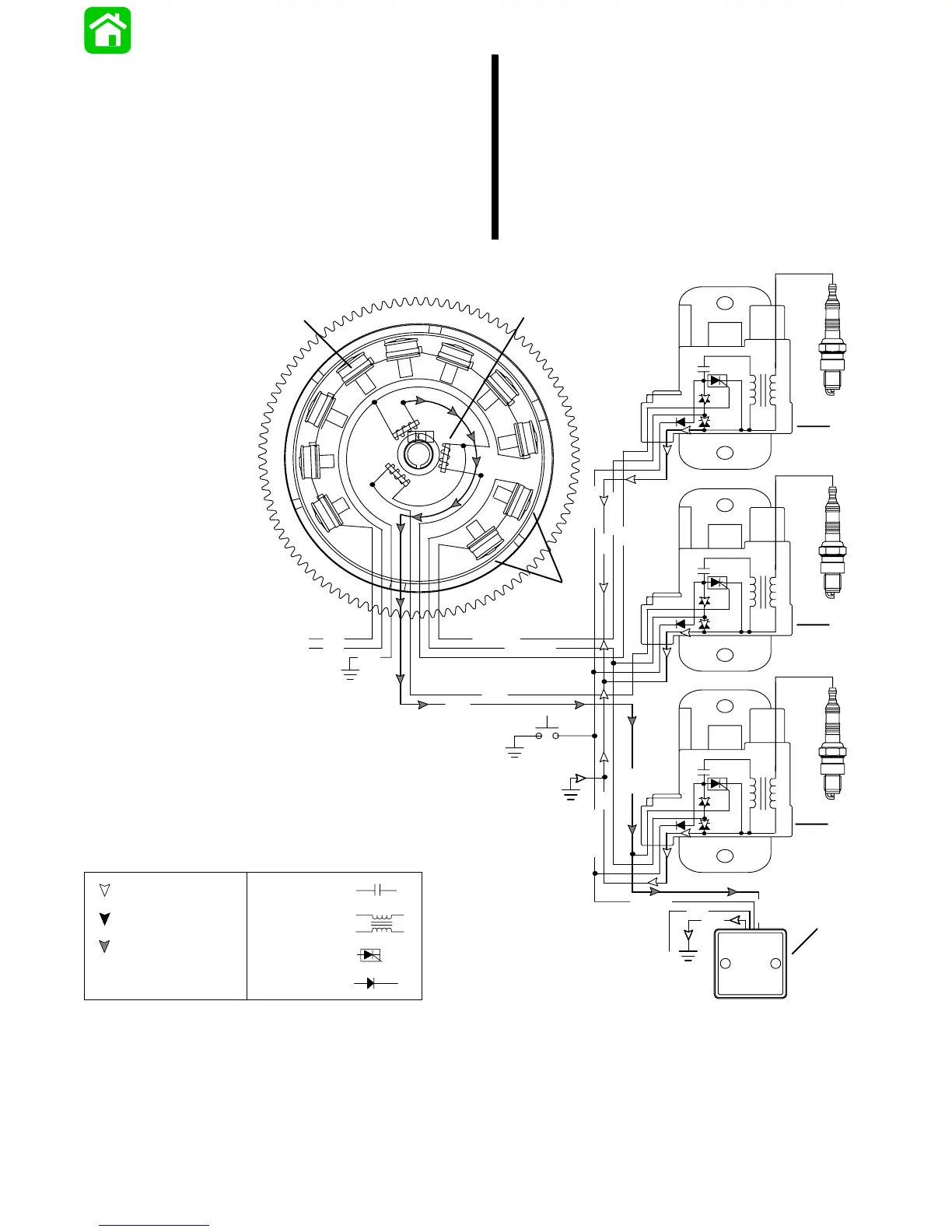
Rev Limiter Circuit
The rev limiter is activated through the PURPLE wire
when the key switch is rotated to the “on” position.
The rev limiter uses a trigger signal (BROWN WIRE)
to determine engine speed or rpm. If the engine
speed exceeds the specified rpm, the rev limiter will
ground out the CDM capacitor charge. The capacitor
voltage flows through the BLACK/YELLOW wires
into the rev limiter and to engine ground through the
BLACK wire.
N
BLK
N
S
S
S
S
S
S
N
N
N
N
N
S
GRN/WHT
WHT/GRN
YEL
YEL
BRN
BLK
WHT
+
+
+
_
_
_
WHT/GRN
PPL
BRN
BLK
BLK/YEL
BRN
BLK/YEL
BLK
BLK/YEL
2
3
PPL
a
b
c
d
e
f
g
h
i
j
1
Return Voltage
CAPACITOR-
Source Voltage
COIL-
SCR-
DIODE-
Trigger Voltage
a - Battery Charging Coils
b - Trigger Coils
c - Capacitor Charge Coils
d - CDM #1
e - CDM #2
f - CDM #3
g - Rev Limiter
h - PURPLE Lead to Ignition Switch
 Loading...