F
THE
GEARBOX.------------------
Extract
the
split pin from
the
nut retaining
the
drive
flange at
the
rear
of
the
gearbox sliding shaft and
remove
the
nut and plain washer.
Remove
the
six nuts securing
the
top
cover assembly
to
the
gearbox and
the
four
bolts and spring washers
securing
the
remote
control cover assembly
to
the
gearbox
extension.
Remove
the
three
selector
springs.
USing
the
extractor,
Tool No. T.IOS (Section Q).
withdraw
the
propeller shaft driving flange. It is
advisable
to
use an
extractor
of this
type
to
avoid
Fig. F.2.
A plug
threaded
into
the
drain plug hole is used
to
hold
the
gearbox
in
the
vl"e.
distortion of
the
flange face. Before doing so, it is
advisable
to
mark both
the
flange and
the
shaft so
that
they
can be replaced in exactly
the
same position.
Detach
the
speedometer
drive housing from
the
right-hand side of
the
gearbox.
Care
should be
exercised
not
to damage
the
paper
gasket on tile Joint
face of
the
housing.
Extract
the
lock-wire from
the
eight square-headed
screws locking
the
gear shifters and stops
to
the
selector shafts and remove
the
screws.
Slacken
the
nuts and
set
bolts securing
the
gearbox
rear
casing to
the
gearbox and withd raw sufficiently
to
allow
the
gear shifters
to
be removed from
the
ends
of
the
selector shafts.
Remove
the
nuts and
set
bolts completely and with-
draw
the
gearbox rear casing from
the
gearbox.
On early type gearboxes withdraw
the
selector
shafts 0 ne at a ti me, takl ng care not
to
lose
the
se
lector
lock balls in
the
process. Later models have a third
and
top
selector shaft
extended
at Its front end and
fitted with a clrcllp
to
prevent
its accidental wlth-
F.2
drawal and
the
loss of
the
synchromesh balls. In this
case
the
cirelip must, of course. be removed before
the
shaft can be withdrawn. This also makes It
imperative to remove
the
gearbox from
the
engine
before dismantling.
Now
lift
out
the
selector forks.
Referen ce to page E.IO will show
the
interlocklng
mechanism of
the
shifter balls. Observe
the
correct
position of
the
gear shifters and stops on
the
selector
spindles as shown in
the
plan view of
the
shifters and
shafts.
Remove
the
layshaft spindle locating screw from
the
rear of
the
gearbox.
Extract
the
layshaft spindle by tappl ng it at
the
forward end with a suitable copper
or
brass drift.
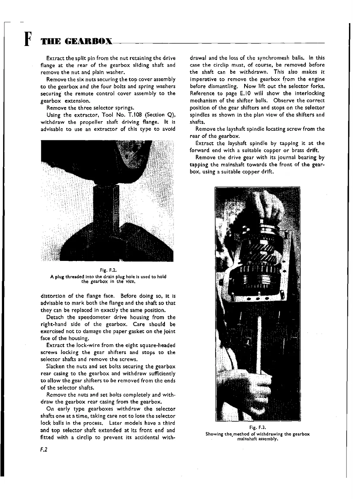
Remove
the
drive gear with its journal bearing by
tapping
the
malnshalt
towards
the
front
of
the
gear-
box, using a suitable
copper
drift.
Fig. F.3.
Showing
the.
method of withdrawing
the
gearbox
malnshaft assembly.
Wishvilles Classic
Automobile Library

 Loading...


