SECTION E
General Description.
Section No. E.I
Running adjustments.
Section No.
E_2
Removal of
the
clutch.
Section
No.
E.3
DIsmantling
the
clutch.
Section No. EA
Assembling
the
clutch.
Section No. E.S
Refitting
the
clutch.
Section No.
E.6
Adjusting
the
release levers.
Section No. E.7
Refa<:ing
the
driven plate.
Section No.
E.8
Servicing
the
clutch.
Section No. E.9
8 in.
diameter
clutch.
Section No. E.I0
Introduction of a clutch
control
rod.
E
GENERAL DESCRIPTION
The
clutch is a single
dry
plate Borg & Beck. Type
7A6G up
to
Engine No.
9-107,
Type BB.8/70 from
Engine No.
9"108
and
BB.S/lOA
from Engine No. 30301
onwards, consisting of a driven plate assembly, a
cover
assembly and a
graphite
release bearing assembly.
Driven plate
assembly
ThIs has a flexible
centre
In which
the
spllned hub
is indirectly attached
to
the
clutch plate and
transmits
the
power
and
over-run
through
a
number
of coil
springs held in position by retaining wires.
Two
friction
faCings
are riveted
to
the
clutch plate,
one
on
each side.
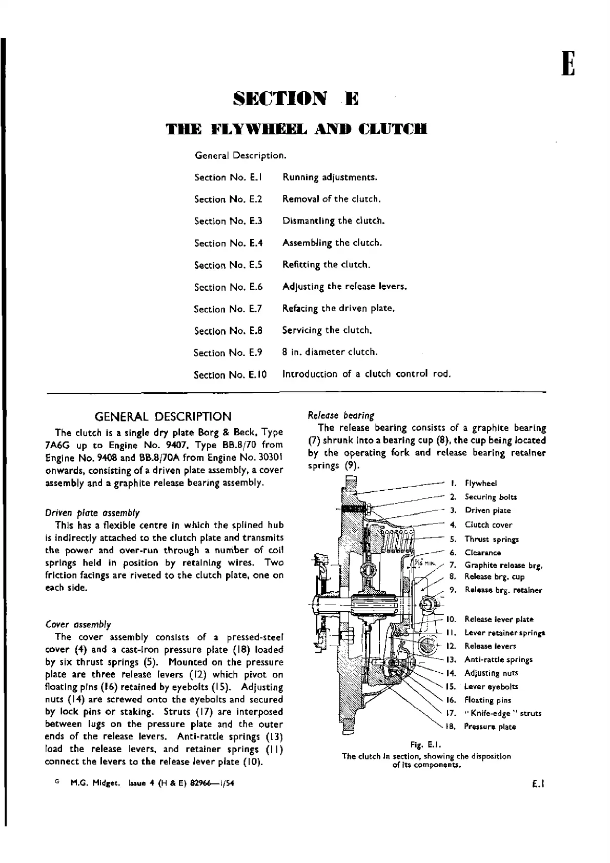
Cover ossembly
The
cover
assembly consists of a pressed-steel
cover
(4) and a cast-Iron
pressure
plate (18) loaded
by six
thrust
springs (5). Mounted on
the
pressure
plate are
three
release levers (12) which pivot on
float Ing pins (16) retained by eye bolts (15). Adjusting
nuts (14)
are
screwed
onto
th e
eyebo
Its and secu red
by lock pins
or
staking.
Struts
(17) are
interposed
between
lugs on
the
pressure
plate and
the
outer
ends of
the
release levers. Anti-
rattle
sprlngs (13)
load
the
release levers, and
retainer
springs
(II)
connect
the
levers to
the
release lever plate (10).
Refease
bearing
The
release bearing consists of a
graphite
bearing
(7)
shrunk
Into a bearing cup (8),
the
cup being located
by
the
operating
fork
and release bearing
retainer
springs (9).
I. Flywheel
2.
Securing bolts
Driven plate
4.
Clutch cover
5. Th
rust
5pri
nZ5
6. Clearance
7.
Graphite release brio
8.
R.elease
brg. cup
9.
ReIease brg.
reta.1
ner
10. Release lever platlt
{_""r-+'''F-"-
...
_~,
II.
Lever
retainer
springs
:~:l
12. Release levers
IJ. Anti-rattle springs
I".
Adjusting
nuts
1S
•.
Lever eyebolts
16. Floating pins
17.
"Knife-edge"
struts
18. Prenu re plate
Fig. E.!.
The
dutch
In section, showing
the
disposltlon
of Its components.
G
M.G. Midget.
lAue"
(H & E)
82%6-1/54
£.1
Wishvilles Classic
Automobile Library

 Loading...


