N
ELE~TRI(;AL
EqUIPME~T-------------
Section
N.27
THE"
CORRECT-ACID-LEVEL"
DEVICE
Correct-acid-Ievel devices have been fitted as
standard
to
the
batteries
in a
number
of models,
one
of
these
devices being located in each cell filler hole.
The
method of topping up a
battery
fitted with
these
is shown in Fig. N.32. It will be seen
that
the
weI/-
known
"air-trap"
is
the
principle underlying
their
operation.
The device consists of a central
tube
with a per-
forated flange which rests on a ledge in
the
filling
orifice.
When
topping
up,
pour
distilled
water
into the
flange
until no
more
drains th rough into
the
cell and
the
water
begins
to
rise i0 th e flange. This
will happen when
the
electrolyte
level reaches
the
A Q
Fig. N.32.
The
operation
of
the"
correct-add-level"
device.
bottom
of
the
central
tube,
thereby
preventing
further
escape of air displaced by
the
topping
up
water
1ntroduced. By lifting
the
tube
slightly
the
small
amount
of
water
held in
the
flange will drain
into
the
cell and
the
electrolyte
level will
then
be
correct.
The illustration (Fig.
N.n)
shows
:-
(a) Electrolyte level below normal. Pour dis-
tilled
water
into
the
flange
around
the
central
tube.
(b) Cease pouring
when
the
water
ceases
to
flow
through
the
flange and begins
to
rise above
it.
The
electrolyte
level is now controlled
by
the
air lock.
N.24
(c)
Release
the
water
which has collected in
the
flange by lifting
the
tube
slightly.
The
electrolyte
level is
then
correct.
Section
N.28
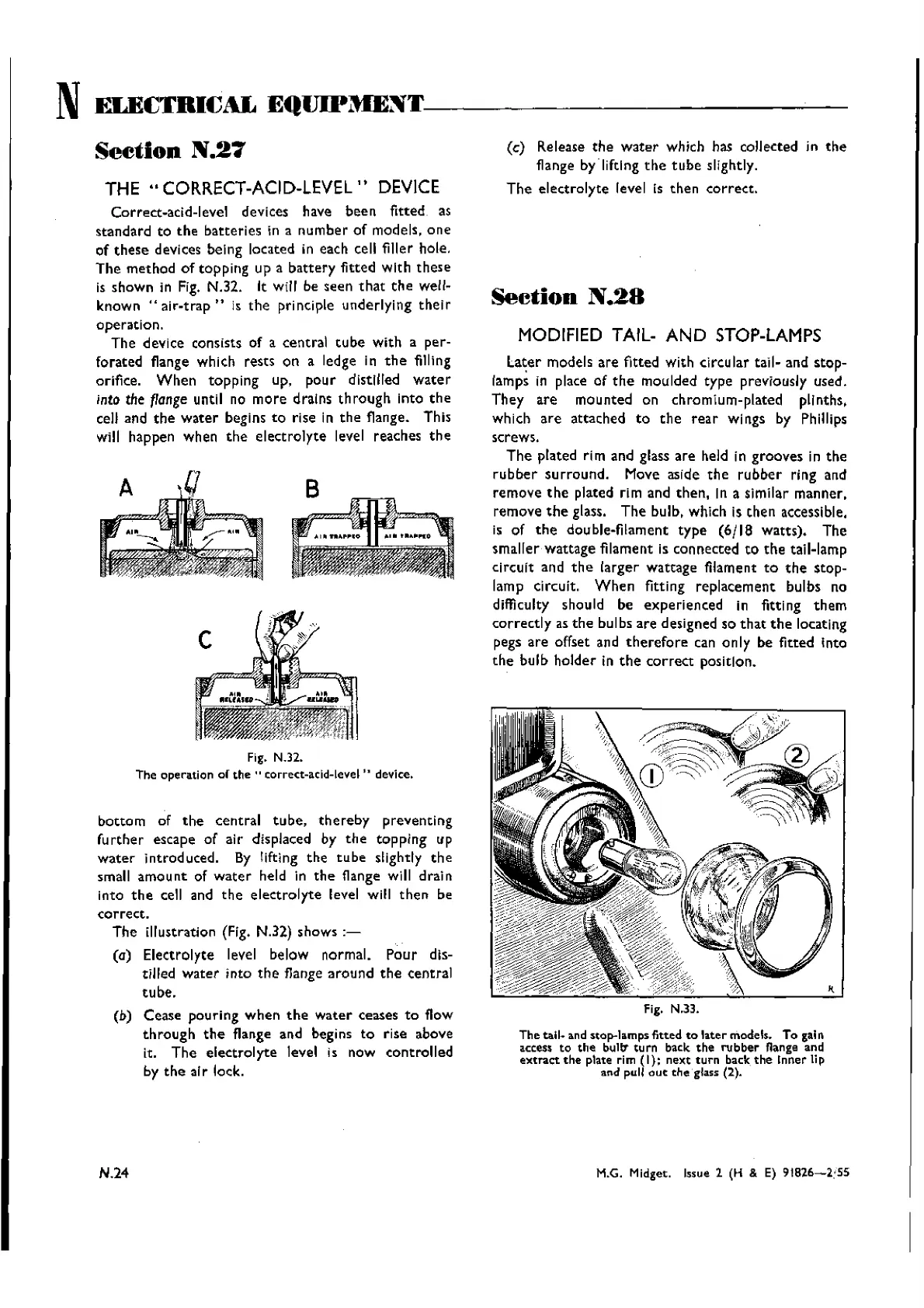
MODIFIED TAIL-
AND
STOP-LAMPS
La~er
models
are
fitted with circular tall- and stop-
lamps in place of
the
moulded type previously used.
They
are
mounted on chromium-plated plinths.
which
are
attached
to
the
rear
wings by Phillips
screws.
The
plated rim and glass
are
held in grooves in
the
rubber
surround.
Move aside
the
rubber
ring and
remove
the
plated rim and
then,
In a slrnllar manner,
remove
the
glass.
The
bulb, which is
then
accessible.
is of
the
double-filament
type
(6/18
watts).
The
smaller
wattage
filament is connected
to
the
tail-lamp
circuit and
the
larger
wattage filament
to
the
stop-
lamp circuit.
When
fitting
replacement
bulbs no
d
iffi
cuIty shouId be
expe
rien
ted
in fitti ng th em
correctly
as
the
bulbs
are
designed so
that
the
locating
pegs
are
offset and
therefore
can only be fitted Into
the
bulb
holder
in
the
correct
position.
fig. N.33.
The
tall.
and stop-lamps
fitted
to
later
models. To galR
access
to
th a bu
111
tu rn back
the
ru b
ber
nan ge and
extract
the
plata rim
(I);
next
turn
back
the
Inner Ii p
and pull
out
the
glass (2).
M.G. Midget. Issue 1 (H & E)
91826-2:55
Wishvilles Classic
Automobile Library

 Loading...


