G
TIlE
PROPELIJER
SIIAF"'r-----------
Section
G.7
REPLACEMENT
OF THE
PR.OPELLER
SHAFT
Wipe
the
faces of
the
flanges clean, and place
the
propeller
shaft In position on
the
car. Ensure
that
A
the
flange registers engage correctly and
that
the
joint faces bed down evenly all round. also
that
the
markings. made on
the
flanges on removal. coincide.
Insert
the
bolts and see
that
all th e nuts. wh lch
are
of
the
self-locking type. are evenly and securely
tightened. The sliding Joint is always placed at
the
gearbox
end.
B
D
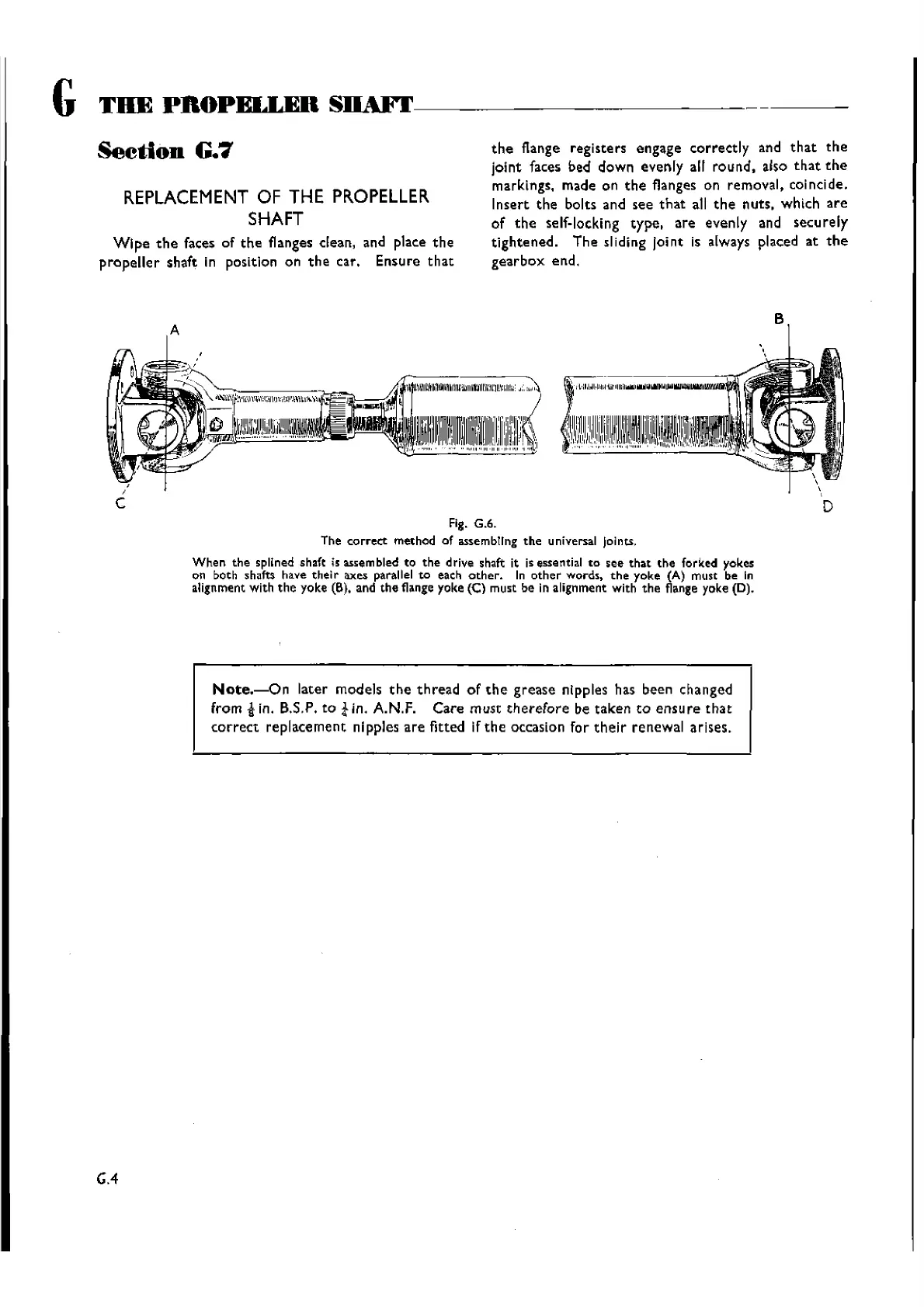
Fig. G.6.
The
correct
method of assembtrng
the
universal Joints.
When
the
spllned shaft is assem bled to
the
drive shaft it is essential
to
see
that
the
forked yokes
on both shafts have
their
axes parallel
to
each
other.
In
other
words.
the
yoke (A) must be In
alignment with
the
yoke (6), and
the
flange yoke (C) must be in alignment with
the
flange yoke (D).
Note.-On
later models
the
thread
of
the
grease nipples has been changed
from .gIn. B.S.P. to
tin.
A.N.F.
Care
must
therefore
be taken
to
ensure
that
correct
re pIacement nipples
are
fitted if th e occasion for th eIr re newal arises.
GA
Wishvilles Classic
Automobile Library

 Loading...


