-------------TUE
BRAKING
SYSTEM
M
Section
M.9
REMOVAL OF THE WHEEL CYLINDER
Front
Raise
the
front
of
the
car
and
remove
the
hub
cap
and
road
wheel.
Remove
the
brake-drum
and
hub
assembly as
detailed
in Section
K.12.
Draw
the
brake-shoes
apart
until
the
assembly can
be lifted
from
the
wheel
cylinders
and
brake
plate.
Release
the
flexible
hose
as
detailed
In Section
M.13.
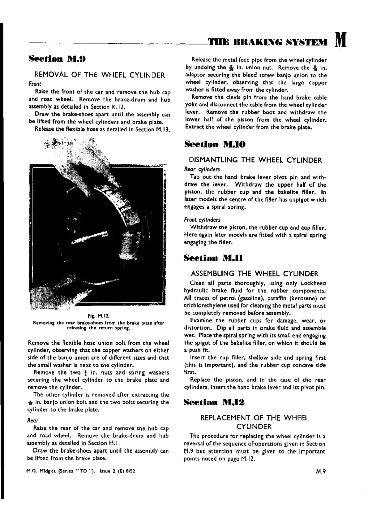
Fig. H.I2.
RemoYlng
tile
rear
brake-shoes from
the
brake plate
after
releasing
the
return
spring.
Remove
the
flexible
hose
union
bolt
from
the
wheel
cylinder,
observing
that
the
copper
washers
on
either
side
of
the
banjo union
are
of
different
sizes and
that
the
small
washer
is
next
to
the
cylinder.
Remove
the
two
t in.
nuts
and
spring
washers
securing
the
wheel
cylinder
to
the
brake
plate
and
remove
the
cylinder.
The
other
cylinder
is
removed
after
extracting
the
-A
In. banjo union
bolt
and
the
two
bolts
securing
the
cylinder
to
the
brake
plate.
Roor
Raise
the
rear
of
the
car and
remove
the
hub
cap
and
road
wheel.
Remove
the
brake-drum
and hub
assembly
as detailed in Section H.1.
Draw
the
brake-shoes
apart
until
the
assembly can
be lifted
from
the
brake
plate.
M.G. Midg
et
(Series
..
TO . '), Issue 2 (E) 8/52
Release
the
metal feed
pipe
from
the
wheel
cylinder
by undoing
the
1lr
In. union nut. Remove
the
-&
in.
adaptor
securing
the
bleed
screw
banjo
union
to
the
wheel
cylinder.
observing
that
the
·Iarge
copper
washer
Is fitted away from
the
cyJinder.
Remove
the
clevis pin
from
the
hand
brake
cable
yoke
and
disconnect
the
cable
from
the
wheel
cylinder
lever. Remove
the
rubber
boot
and
withdraw
the
lower
half
of
the
piston
from
the
wheel
cylinder.
Extract
the
wheel
cylinder
from
the
brake
plate.
Seetlon
M.IO
DISMANTLING THE WHEEL CYLINDER
Reor
cytinders
Tap
out
the
hand
brake
lever
pivot
pin and
with-
draw
the
lever.
Withdraw
the
upper
half
of
the
piston,
the
rubber
cup
and
the
bakelite
filler. In
later
models
the
centre
of
the
filler has a
spigot
which
engages
a spiral
spring.
Front
cylinders
Withdraw
the
piston,
the
rubber
cup and
cup
filler.
Here
again
later
models
are
fitted
with
a spiral
spring
engaging
the
filler.
Section
M.ll
ASSEMBLING THE WHEEL CYLINDER
Clean all
parts
thoroughly,
using
only
Lockheed
hydraulic
brake
fluid
for
the
rubber
components.
All
traces
of
petrol
(gasoline), paraffin
(kerosene)
or
trichlorethylene
used
for
cleaning
the
metal
parts
must
be
completely
removed
before
assembly.
Examine
the
rubber
cups
for
damage.
wear.
or
distortion.
Dip all
parts
in
brake
fluId and assemble
wet.
Place
the
spiral
spring
with
its small
end
engaging
the
spigot
of
the
bakelite
filler, on which it
should
be
a push fit.
Insert
the
cup filler.
shallow
side and
spring
first
(this is
important).
and
the
rubber
cup
concave sIde
first.
Replace
the
piston. and in
the
case of
the
rear
cylinders.
Insert
the
hand
brake
lever
and Its pivot pin.
Seetlou
M.12
REPLACEMENT OF THE WHEEL
CYLINDER
The
procedure
for
replacing
the
wheel
cylinder
is a
reversal
of
the
seq uenee of-operatlons gIven in Secti 0 n
{-1.9
but
attention
must
be given to
the
j
mportant
pol nts
noted
0 n page M.12.
M.9
Wishvilles Classic
Automobile Library

 Loading...


