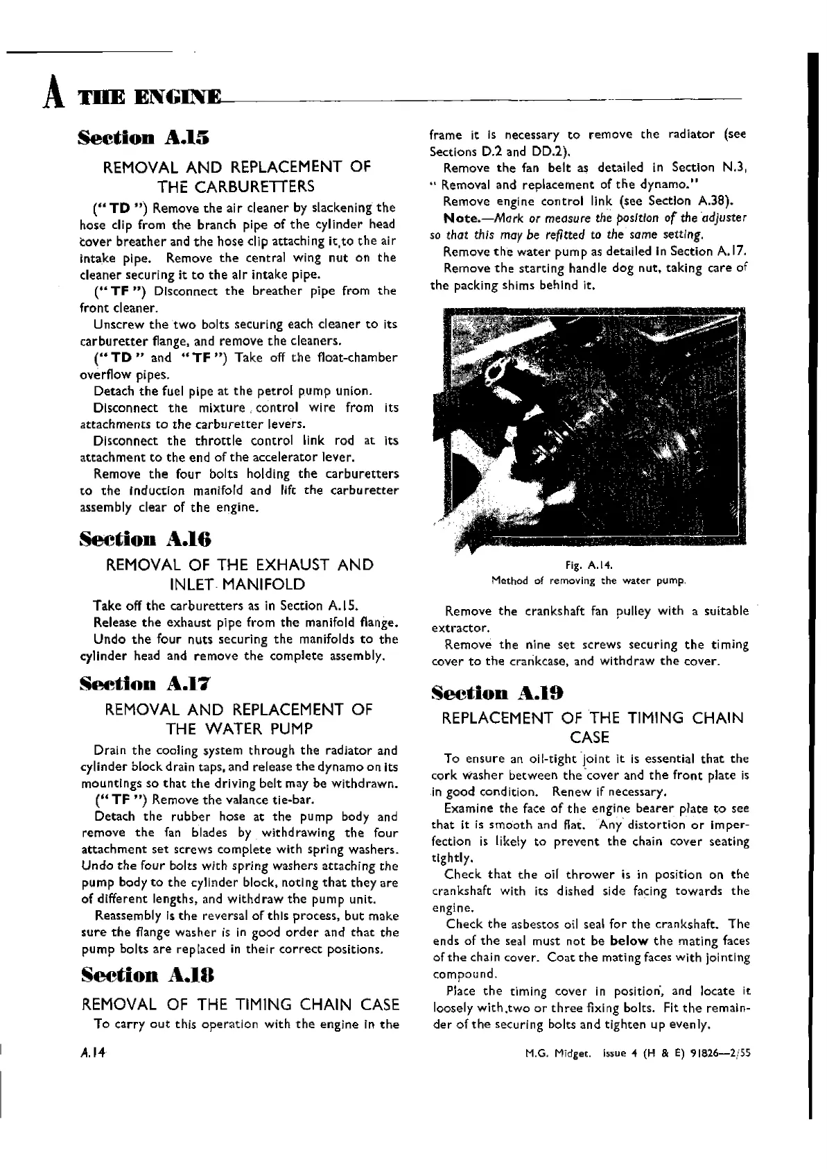
Fig. A.14.
Method of removing the
water
pump.
Remove
the
crankshaft fan pulley with a suitable
extractor.
Remove
the
nine
set
screws securing
the
timing
cover
to
the
crankcase, and withdraw
the
cover.
frame it Is necessary
to
remove
the radiator (see
Sections D.2 and DD.2).
Remove
the
fan
belt
as detailed in Section N.3,
.. Removal and
replacement
of
tne
dynamo."
Remove engine
control
link (see Section A.38).
Note.-Mark
or
measure
the positIon
of
the 'adjuster
so that this may be refitted to the same setting.
Remove t he
water
pump as detailed in Section
A.17.
Remove
the
starting
handle dog nut, taking care of
the
packing shims behind it.
section
A.l6
REMOVAL OF THE EXHAUST
AND
INLET- MANIFOLD
Take off
the
carbu
retters
as in Section A.IS.
Release
the
exhaust
pipe from
the
manifold flange.
Undo
the
four
nuts
securing
the
manifolds
to
the
cylinder head and
remove
the
complete assembly.
A
mE
ENGINE~----------,--
Section
A.15
REMOVAL
AND
REPLACEMENT OF
THE CARBURETTERS
(U
TO
")
Remove
the
air
cleaner by slackening
the
hose clip from
the
branch pipe of
the
cylinder head
cover
breather
and
the
hose clip attaching
it,to
the
air
intake pipe. Remove
the
central wing
nut
on
the
cleaner securing it
to
the
air intake pipe.
(.. TF
")
Dlsconnect
the
breather
pipe from
the
front
cleaner.
Unscrew
the
two
bolts securing each
cleaner
to
its
carburetter
flange, and remove
the
cleaners.
(U
TO
.. and ..
TF
")
Take off
the
float-chamber
overflow pipes.
Detach
the
fuel pipe at
the
petrol
pump union.
Disconnect
the
mixture,
control
wire
from its
attachments
to
the
carburetrer
levers.
Disconnect
the
throttle
control link rod at its
attachment
to
the
end of
the
accelerator
lever.
Remove
the
four
bolts holding
the
carburetters
to
the
Induction manifold and lift
the
carburetter
assembly clear of
the
engine.
Seetion
A.17
REMOVAL
AND
REPLACEMENT OF
THE WATER PUMP
Drain
the
cooling system
through
the
radiator
and
cylinder block drain taps, and release
the
dynamo on its
mountings so
that
the
driving belt may be Withdrawn.
(U
TF
")
Remove
the
valance tie-bar.
Detach
the
rubber
hose at
the
pump body and
remove
the
fan blades by withdrawing
the
four
attachment
set
screws
complete
with
spring
washers.
Undo
the
four bolts with
spring
washers attaching
the
pump body
to
the
cylinder block, noting
that
they
are
of different lengths, and
withdraw
the
pump unit.
Reassembly [s
the
reversal of this process,
but
make
sure
the
flange washer is in good
order
and
that
the
pump
bolts
are
replaced in
their
correct
positions.
Section
A.lO
REMOVAL OF THE TIMING
CHAIN
CASE
To carry
out
this
operation
with
the
engine in
the
A.14
Section
...
"-.19
REPLACEMENT OF THE TIMING
CHAIN
CASE
To
ensure
an oil-tight -joint it is essential
that
the
cork
washer
between
the
'cover
and
the
front
plate is
in good condition. Renew if necessary.
Examine
the
face of
the
engine
bearer
plate
to
see
that
it is
smooth
and flat. Any' distortion
or
1m
per-
fection is likely to
prevent
the
chain
COver
seating
tightly.
Check
that
the
oil
thrower
is in position on
the
crankshaft With its dished side facing
towards
the
engine.
Check
the
asbestos oil seal
for
the
crankshaft. The
ends of
the
seal must not be
below
the
mating faces
of
the
chain cover.
Coat
the
mating faces with jointing
compound.
Place
the
timing cover in position', and locate it
loosely
with.two
or
three
fixing bolts. Fit
the
remain-
der
of
the
securing bolts and tighten up evenly.
M.G. Midget. Issue 4 (H & E)
91826-2/55
Wishvilles Classic
Automobile Library

 Loading...


