-----
---------
TIlE
ENGINE
A
Remove
the
valve
cover
and
rocker
gear
from
the
cylinder
head as indicated in Section A.B,
when
the
push-rods
may be withdrawn.
Note.-It
is advisable to keep these in order
of
f'emoval.
INlET
VALVES
Fig.
A.II.
This illustration shows
the
numbering of
the
valves.
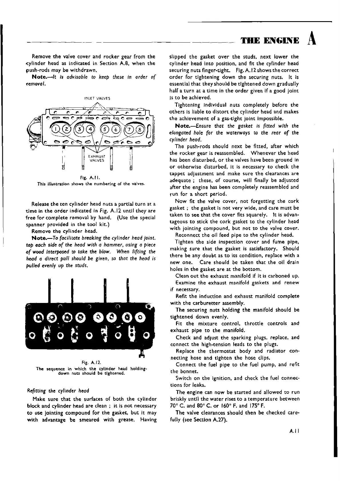
Release
the
ten
cylinder head nuts a partial tu rn at a
ti
me in
the
order
indicated in Fig. A.
12
until
they
are
free
for
complete
removal by hand. (Use
the
special
spanner
provided
in
the
tool
kit.)
Remove
the
cylinder head.
Note.-To
facilitate breaking the cylinder head joint,
tap each side
of
the head with a hammer, using a piece
of
wood Interposed to take the blow. When lifting the
head a
direct pull
should
be given, so that the head is
pulled evenly up the studs.
Fig. A.12.
The sequence in which
the
cylinder head holding-
down
nuts should be tightened.
Refitting the cylinder head
Make
sure
that
the
surfaces of both
the
cylinder
block
and cylinder head
are
clean;
it is
not
necessary
to
use jointing compound for
the
gasket,
but
it may
with
advantage be
smeared
with
grease. Having
slipped
the
gasket
over
the
studs,
next
lower
the
cylinder head
into
position, and fit
the
cylinder head
secu ring
nuts f nger-tight. Fig.A.12 shows
the
correct
order
for tightening down
the
securing nuts. It Is
essential
that
they should be
tightened
down gradually
half a
turn
at
a time in
the
order
given if a good
joint
is
to
be achieved.
Tightening individual nuts completely before
the
others
is liable
to
distort
the
cylinder head and makes
the
achievement of a gas-tight
joint
impossible.
Note.-£nsure
that the gasket is fitted with the
elongated hole for the waterways to the reor
of
the
cylinder head.
The push-rods should
next
be fitted, after which
the
rocker
gear is reassembled.
Whenever
the
head
has been
disturbed,
or
the
valves have been ground in
or
otherwise
disturbed, it is necessary
to
check
the
tappet
adjustment
and make
sure
the
clearances
are
adequate;
these.
of
course, will finally be ad]usted
after
the
engine has been completely reassembled and
run
for a
short
period.
Now fit
the
valve cover, not forgetting
the
cork
gasket;
the
gasket is not very wide, and care must be
taken
to
see
that
the
cover
fits squarely. It is advan-
tageous
to
stick
the
cork
gasket to
the
cylinder head
with jointing compound,
but
not
to
the
valve cover.
Reconnect
the
oil feed pipe
to
the
cylinder head.
Tighten
the
side inspection
cover
and fume pipe,
making
sure
that
the
gasket is satisfactory. Should
there
be any
doubt
as
to
its condition, replace with a
new one.
Care
should be taken
that
the
oil drain
holes in
the
gasket
are
at
the
bottom.
Clean
out
the
exhaust
manifold if it is carboned up.
Examine
the
exhaust
manifold gaskets and
renew
if necessary.
Refit
the
induction and
exhaust
manifold
complete
with
the
carburetter
assembly.
The securing nuts holding
the
manifold should be
tightened
down evenly.
FIt
the
mixture
control.
throttle
controls and
exhaust
pipe
to
the
manifold.
Check and adjust
the
sparking plugs, replace, and
connect
the
high-tension leads
to
the
plugs.
Replace
the
thermostat
body and radiator con-
necti ng hose and
tlghte
n
the
hose elips,
Can n
eet
the
fuel pipe to
the
fueI pump, and refit
the
bonnet.
Switch on
the
ignition, and check
the
fuel connec-
tions
for leaks.
The engine can now be
started
and allowed to run
briskly untl!
the
water
rises
to
a
temperature
between
70° C. and 80° C.
or
160°
F. and
175
0
F.
The valve clearances should
then
be checked care-
fully (see Section
A.27).
A.II
Wishvilles Classic
Automobile Library

 Loading...


