GENERAL
INFORMATION
(SERIES U
TO
")
GEAR
POSITIONS
The
gearbox has four forward speeds, with synchromesh on second.
third
and top.
The
gear lever posItions
are
shown In
the
lllustratlon below.
To engage
reverse
gear, move
the
gear lever
to
the
extreme
right of its neutral posltlon:
exert
sufficient pressure
to
overcome
the
resistance
of
the
spring-loaded
stop,
and move
the
lever
rearwards.
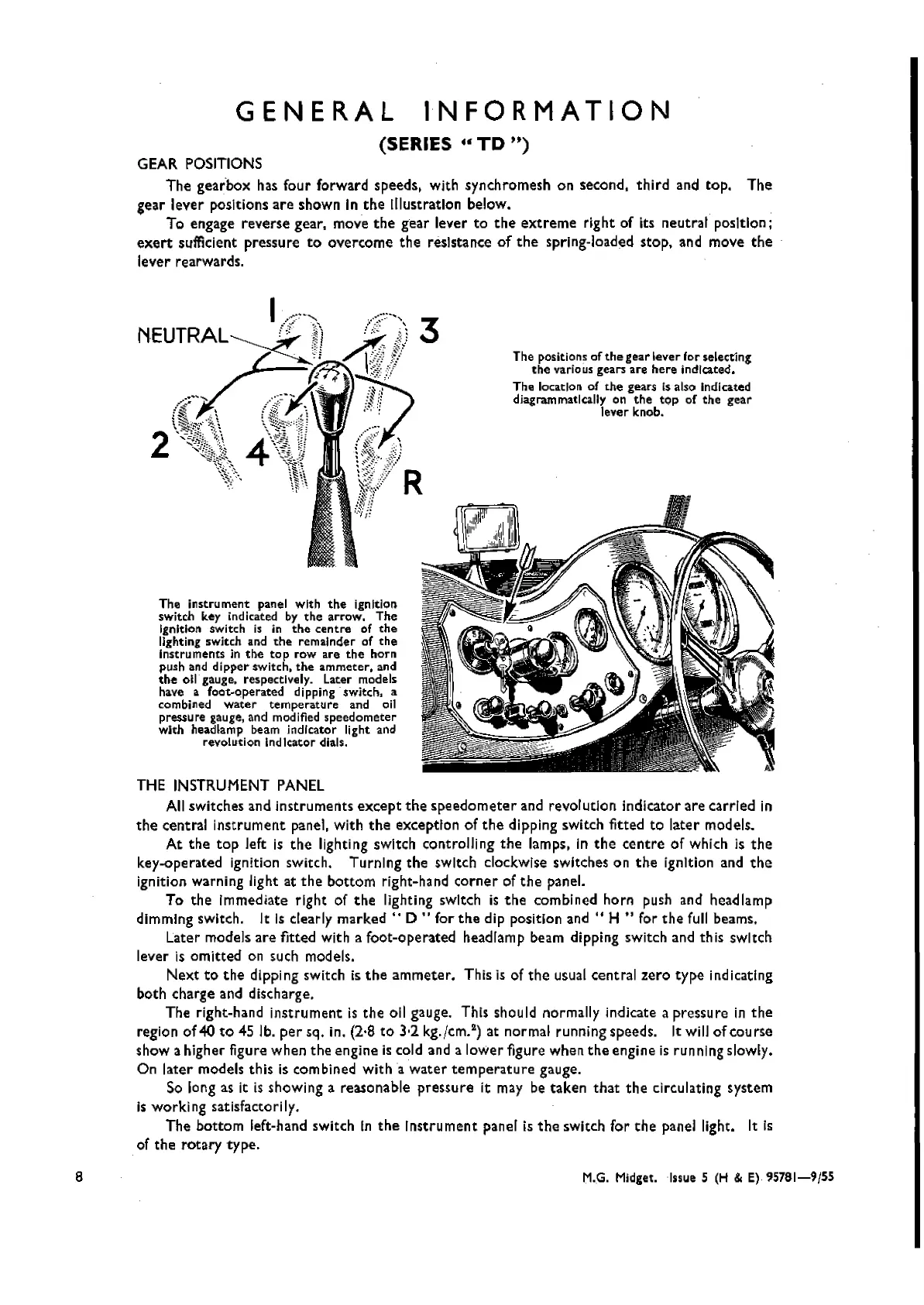
The
instrument
panel with
the
ignition
switch key indicated by
the
arrow.
The
Ignition switch is in
the
centre
of
the
lighting switch and
the
remainder of
the
Instruments in
the
top
row
are
the
horn
push and
dipper
SWitch,
the
ammeter. and
the
011
gauge. respectively. Later models
have a fooc-operated dipping switch, a
combined
water
temperature
and oil
pressure gauge, and modified
speedometer
with headlamp beam indicator light and
revolution
indltator
dials.
The positions of
the
gearlever lor selecting
the
varia us gears
are
here
indicated.
The location of
the
gears Is also indicated
diagrammatically on
the
top
of
the
gear
lever knob.
8
THE
INSTRUMENT
PANEL
All switches and
instruments
except
the
speedometer
and revolution indicator are carried in
the
central
instrument
panel, with
the
exception of
the
dipping switch fitted
to
later models.
At
the
top
left is
the
lighting swltch controlling
the
lamps, In
the
centre
of which is
the
key-operated ignition switch. Turning
the
switch clockwise switches on
the
ignItion and
the
ignition warning light at
the
bottom
right-hand
corner
of
the
panel.
To
the
immediate right of
the
lighting swItch is
the
combined horn push and headlamp
dimming switch. It Is clearly
marked"
D .. for
the
dip position
and"
H " for
the
full beams.
Later models
are
fitted with a foot-operated headlamp beam dipping switch and this switch
lever is
omitted
on such models.
Next
to
the
dipping switch is
the
ammeter.
This is of
the
usual central
zero
type
indicating
both charge and discharge.
The right-hand
instrument
is
the
oil gauge. Thts should normally indicate a pressure in
the
region of 40
to
45 lb.
per
sq. in. (2·8
to
3·2 kg./em.
2
)
at normal running speeds. It will of cou rse
show a higher figure when
the
engine is cold and a lower figure when
the
engine is running slowly.
On
later
models
this
Is combined
with
a
water
temperature
gauge.
So long as it is showing a reasonable
pressure
it may be
taken
that
the
circulating system
is working satisfactorily.
The
bottom
left-hand switch In
the
instrument
panel is
the
switch
for
the
panel light. It is
of
the
rotary
type.
M.G. Midget. Issue 5 (H & E)
95781-9/55
Wishvilles Classic
Automobile Library

 Loading...


