A
THE
ENGINE
slotted nuts. This enables
the
crank.shaft
to
be lifted
from
the
crankcase.
Having cleaned
the
oilways drilled in
the
crankshaft
and
the
bearing journals,
the
new bearings are placed
in position on
their
locating dowels, and
the
crank-
shaft replaced. No scraping is required as
the
bearings
are
machlned to give
the
correct
diametrical clearance
offrom
·0008 in.
to
·003 In. (,02mm.
to
·075 mm.) and
the
side clearanceof from ·0014in. to ·0037in.
(,035
mm.
to
·095 mm.) on
the
centre
bearing. The end bearings
have no end location.
In
the
case of a run bearing, it Is always advisable
to
clean
out
all
the
oJlways In
the
crankshaft and block.
Then wash
out
the
engine base with paraffin.
Seetion
A.8
REMOVAL
AND
REPLACEMENT OF
THE ROCKER
ASSEMBLY
Remove
the
air
cleaner. Detach
the
cylinder head
cover
by removing
the
two
retaining hand nuts and
fibre washers.
Tap back
the
tabs of
the
lock washers from
the
eight
rocker-shaft bracket fixing bolts and unscrew
the
four
1lr
in. and
four!
in. bolts gradually, a
turn
at a time,
until all load has been taken off
the
rocker-shaft, then
completely unscrew
the
bolts.
This
is
important.
Remove
the
rocker
assembly, complete with bracket
and rockers, and wIthdraw
the
eIght push-rods,
marklng
them
so
that
they
may be replaced in
the
same
positions. To dismantle
the
rocker-shaft assembly.
remove
the
two
retaining clips at
either
end of
the
shaft and slide
the
rockers, brackets and springs from
the
shaft. Care should be-taken not
to
lose
the
shaft
bracket washers and a note made of
the
fact
that
the
front
and rear washe rs are .. D "-shaped, whereas
the
washers fitted
to
the
centre
brackets are of
the
normal
pattern
and engage with slots in
the
shaft.
A
note
should also be made In
the
case of later
engines.
that
thrust
washers are fitted
between
the
spacing springs and
the
end
bearing faces of
the
rockers.
Remove
the
plugs from each end of
the
shaft so
that
the
oilways may be cleaned.
Reassembly and replacement Is a reversal of
the
above procedure,
but
care must be taken
to
replace
rockers and springs correctly on
the
shaft.
Section
A.9
REMOVAL
AND
REPLACEMENT OF
THE CYLINDER HEAD
Drain
the
water
system by opening
the
tap at
the
bottom
of
the
radiator and
the
tap
in
the
cylinder
block Immediately below and in front of
the
exhaust
manifold (see Section 0.1).
Remove
the
bonnet
after taking
out
the
two
screws
at
the
rear
end of
the
bonnet
hinge.
Detach high-tension cables from
the
sparking plugs.
Remove
the
sparking plugs, being careful
not
to
break
or
damage
the
porcelain insulators.
Disconnect
throttle
controls and mixture controls.
Uncouple
the
exhaust pipe from
the
manifold.
Disconnect
the
fuel pipe from
the
fuel pump.
Disconnect
the
breather
pipe connection.
Slacken
the
hose clips and remove
the
air
cleaner.
remembering
that
the
central wing
nut
also serves to
hold
the
cleaner
onto
the
air intake pipe, and
that
It
is full of oil.
Disconnect
the
Intake pipe steady on
the
manifold.
Undo
the
four bolts holding
the
intake pipe and
remove
it
complete. Remove
the
bolt clipping
the
exhaust
pipe to
the
gearbox.
Remove
the
four nuts securing
the
induction and
exhaust manifold
to
the
cylinder head and
withdraw
the
clamps
and manifold.
Loosen
the
top
clips on
the
thermostat
by-pass pipe.
Take off
the
top
radiator hose and
thermostat.
Remove
the
011
feed pipe
for
the
rocker gear from
its
attachment
to
the
cylinder head.
It Is also necessary
to
slacken
the
fume pipe and
remove
the
SideInspection cover. If
the
gasket of this
cover
is damaged. a new one must be fitted before
the
engine Is ru n.
A,IO
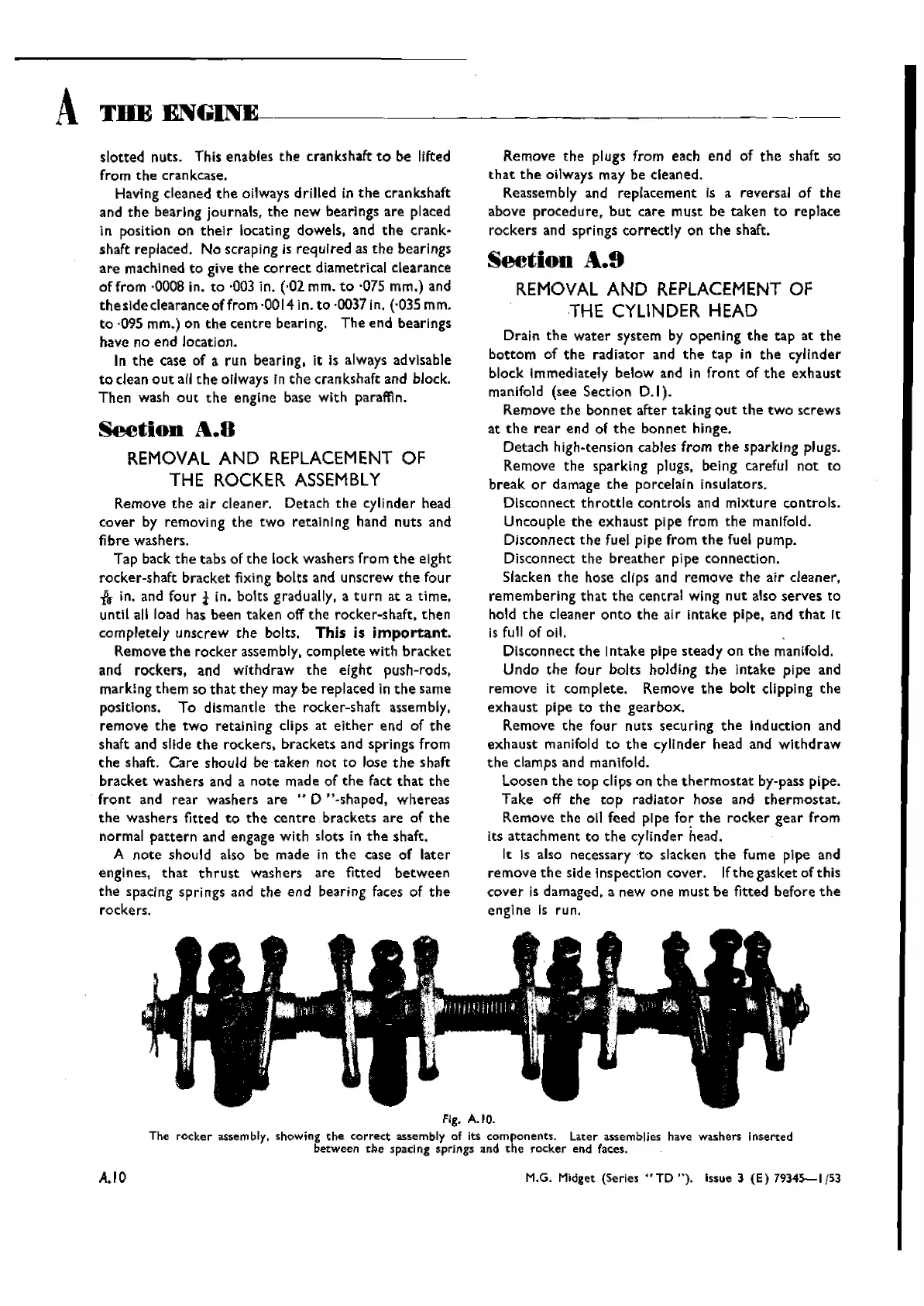
Fig. A.IO.
The
rocker
assembly. showing
the
correct
assembly of its components. Later assemblies have washers Inserted
between
the
spacing springs and
the
rocker
end faces.
M.G. Midget (Series
"TD
").
Issue 3
(E)
7934S-lj53
Wishvilles Classic
Automobile Library

 Loading...


