L
THE
HYDRAULIC
DAMPEBS-------------
Seetion
L.2
REMOVAL
AND
REPLACEMENT
OF
REAR
HYDRAULIC
DAMPERS
Jack up
the
rear
of
the
car
and
remove
the
road
wheel.
Remove
the
nut
and
spring
washers
securing
the
damper
arm
to
the
bracket
on
the
rear
axle.
Remove
the
two
nuts
and
spring
washers
from
the
two
bolts
securing
the
damper
to
the
chassis side-
member.
Slide back
the
two
bolts
and
withdraw
the
damper.
Replacement
is
carried
out
in
the
reverse
manner
to
that
detailed
for
removal,
but
before
fitting
the
link
to
the
bracket
on
the
axle, It is advisable
to
work
the
lever
arm
a few
times,
up and
down,
through
its
full
stroke.
As
these
dampers
are
used
through
nearly
the
complete
available angle of
movement,
it is advisable
when
replacement
dampers
are
fitted
to
check
the
angle of
the
lever
travel.
If
the
levers have been
removed
from
their
splines and replaced In
the
in-
correct
position, a foul may
occur
within
the
damper
mechanism
when
the
car
is
driven.
Note.-When
handling hydraulic
dampers
that have
been
removed
from
the chassis
for
any
purpose,
it is
Important to keep the assemblies upright as [or as
pos-
sible, otherwise air may enter the operating chamber,
resulting in free movement.
Section
L.3
REMOVAL
OF THE
FRONT
DAMPERS
Jack up
the
car
under
the
lower
wishbone
pan till
the
wheel
is clear of
the
ground
on
whichever
side
it
is
wished
to
remove
the
damper.
L.2
Remove
the
wheel
and
detach
the
top
pivot
bolt
for
the
swivel pin. Swing
out
the
hub
unit
clear
of
the
upper
wishbone
and
support
it on a
suitable
stand
to
prevent
straining
the
brake
hose.
Then
unscrew
the
fa ur
set
screws
holding
the
dam per
to
the
chassis(rame.
Section
L.4
TESTING
THE
DAMPERS
If
the
hydraulic
dampers
do
not
appear
to
function
satisfactorily,
the
resistance may
roughly
be
checked
by
bouncing
each
corner
of
the
car
up and
down.
A
uniform
movement
indicates
that
no
attentlon
is
required.
but
if
the
resistance Is
erratic
or
free
movement
of
the
car
is felt,
the
damper
should
be
removed
for
checking and
topping
up.
To
remove
the
rear
hydraulic
dampers
from
the
chassis
see
Section L.2.
Indication
of
their
resistance can be
obtained
by
carrying
out
the
following check.
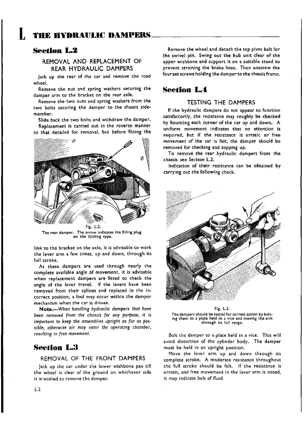
Fig.
L3.
The
dampers should be
tested
for
correct
action by bolt-
ing
them
to a plate held in a vice and moving
the
arm
through
its fu
II
range.
Bolt
the
damper
to
a
plate
held in a vice. This will
avoid
distortion
of
the
cylinder
body.
The
damper
must
be held in an
upright
position.
Move
the
lever
arm
u-p
and
down
through
its
complete
stroke.
A
moderate
resistance
throughout
the
full
stroke
should
be felt. If
the
resistance
is
erratic,
and free
movement
In
the
lever
arm
is
noted,
It may indicate lack
of
fluid.
Wishvilles Classic
Automobile Library

 Loading...


