-------------TDE
FRONT
SUSPENSION K
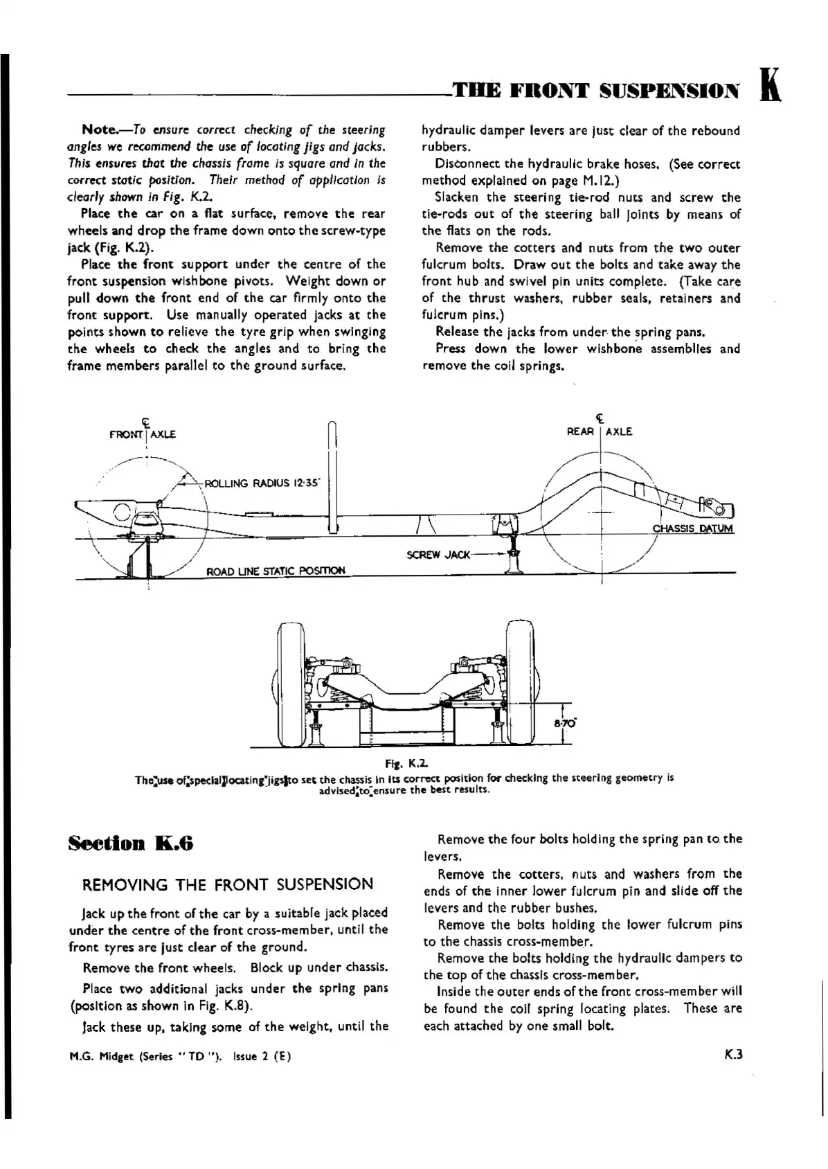
Note.-To
ensure correct checking
of
the steering
angle.s
we recommend the use of locating Jigs and jacks.
This
ensures
that the chassis frame is square and in the
correct static
positTon.
Their method of
appllcQtlon
Is
clearly
shown
in Fig. K.2.
Place
the
car
on a flat surface,
remove
the
rear
wheels
and
drop
the
frame
down
onto
the
screw-type
jack (Fig. K.2).
Place
the
front
support
under
the
centre
of
the
front
suspension wishbone pivots.
Weight
down
or
pull
down
the
front
end of
the
car firmly
onto
the
front
support
. Use manually
operated
jacks at
the
points
shown
to
relieve
the
tyre
grip
when
swinging
the
wheels
to
check
the
angles and
to
bring
the
frame
members
parallel
to
the
ground
surface.
hydraulic
damper
levers
are
just
clear of
the
rebound
rubbers.
Disconnect
the
hydraulic brake hoses. (See
correct
method explained on page M.12.)
Slacken
the
steering
tie-rod
nuts and
screw
the
tie-rods
out
of
the
steering
ball Joints by means of
the
flats on
the
rods .
~emove
the
cotters
and
nuts
from
the
two
outer
fulcrum bolts. Draw
out
the
bolts and
take
away
the
front
hub and swivel pin units
complete.
(Take care
of
the
thrust
washers.
rubber
seals,
retainers
and
fulcrum plns.)
Release
the
jacks
from
under
the
spring
pans.
Press
down
the
lower
wishbonoe assemblies and
remove
the
coil springs.
ROAD UNE
STATIC
POsmoH
1£
F"RONT
I
AXLE
,
/",
- :
-"
. . A ROLLING RADIUS 12'35 '
n
FIg. K.2.
The~s.
of'speelaillocating'jigsito sec
the
chassis In Its
correct
position
fOf'
checking the sceerlng
geomet
ry is
• a - iLdvlsed;to:ensure
the
best
results.
Seedon
K.6
REMOVING
THE
FRONT
SUSPENSION
Jack up
the
front
of
the
car by a suitable jack placed
under
the
centre
of
the
front
cross
-member.
until
the
front
tyres
are
Just
clear
of
the
ground.
Remove
the
front
wheels. Block up
under
chassis.
Place
two
additional jacks
under
the
spring pans
(position
asshown in Fig. K.8).
Jack
these
up. taking some of
the
weight, until
the
M.G.
Midget
(Series .. TO " )0
Issue
2
(E)
Remove
the
four bolts holding
the
spring pan
to
.
the
levers.
Remove
the
cotters
,
nuts
and washers from
the
ends of
the
inner
lower
fulcrum pin and slide off
the
levers and
the
rubber
bushes.
~emove
the
bolts holding
the
lower
fulcrum pins
to
the
chassis cross-member,
Remove
the
bolts holding
the
hydraulic
dampers
to
the
top
of
the
chassis cross-membar,
Inside
the
outer
ends
ofthe
front
cross-member
will
be found
the
coil spring locating plates. These
are
each attached by one small bolt.
K.3
Wishvilles Classic
Automobile Library

 Loading...


