K THE FRONT
SUSPENSION-----
MAINTENANCE
In
ordinary
maintenance it is unlikely
that
it will be
necessary
to
do
more
than
attend
to
replenishment
as
indicated in Section P.6, and check
the
front
wheel
alignment. This Is
the
setting
that
may be affected by
striking high
kerbs
or
similar obstacles.
In view
of
the
Importance
of maintaining
the
correct
steering
geometry
the
use
of
special locating Jigs as
indicated in Fig.
K.2 is
strongly
advised
when
checking
and setting.
Seetion
1i.1
CHECKING
AND
ADJUSTING FRONT
WHEEL ALIGNMENT
When
checking
the
track
width
at
the
front
and
the
rear
of
the
front
wheels, use a suitable
trammel,
or
any special
proprietary
alignment
equipment
available.
The
wheels should run parallel and have no toe-in.
The
correct
setting is
obtained
with equal measure-
ments back and front.
See
that
the
tyres
are
inflated
to
the
correct
pressures.
Set
the
wheels in
the
straight-ahead position.
Set
the
arms of a suitable
trammel
to
the
height of
the
hub
centre.
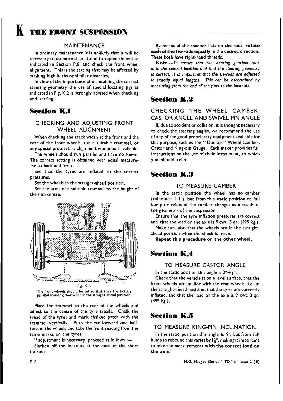
Fig. K.I.
The
front
wheels should be
set
so
that
they
are
exactly
parallel
to
each
other
when in
the
straight-ahead position.
Place
the
trammel
to
the
rear
of
the
wheels and
adjust
to
the
centre
of
the
tyre
treads.
Chalk
the
tread
of
the
tyres
and
mark
chalked patch
with
the
trammel
vertically. Push
the
car forward
one
half-
turn
ef
the
wheels and
take
the
front
reading from
the
same
marks
on
the
tyres.
If
adjustment
is necessary. proceed as follows
:-
Slacken off
the
locknuts at
the
ends of
the
short
tie-rods.
K.2
By means of
the
spanner
flats on
the
rods.
rotate
each
of
the
tie-rods
equally
in th e desired directi
on.
These
both
have right-hand
threads.
Note.-To
ensure that the steering gearbox rack
Is in the
centrClI
position
and that the steering geometry
Is correct, it Is important that the tie-rods
are
adjusted
to exactly
equal
lengths.
This
can be ascertained by
measuring
from
the end
of
the
flats
to the locknuts.
SectIon
K.2
CHECKING
THE
WHEEL
CAMBER,
CASTOR ANGLE
AND
SWIVEL PIN ANGLE
If,due
to
accident
or
collision, It is
thought
necessary
to
check
the
steering
angles, we
recommend
the
use
of any of
the
good
proprietary
equipment
available
for
this purpose, such as
the"
Dunlop"
Wheel
Camber.
Castor
and King-pin Gauge. Each
maker
provides full
Instructions on
the
use of
their
instrument.
to
which
you should refer.
Section
K.3
TO
MEASURE
CAMBER
In
the
static position
the
wheel has no
camber
(tolerance
± 1°),
but
from
this
statlc
position
to
full
bump
or
rebound
the
camber
changes as a
result
of
the
geometry
of
the
suspension.
Ensure
that
the
tyre
Inflation
pressures
are
correct
and
that
the
load on
the
axle is 9
cwt
3 qr. (495 kg.).
Make
sure
also
that
the
wheels
are
In
the
straight-
ahead
posltlon
when
the
check is made.
Repeat
this
procedure
on
the
other
wheel.
See.ion
K.4
TO
MEASURE
CASTOR ANGLE
In
the
statlc position this angle is r±to.
Check
that
the
vehicle Is on a level surface.
that
the
front
wheels
are
in line
with
the
rear
wheels. I.e. in
the
straight-ahead position,
that
the
tyres
are
correctly
inflated, and
that
the
load on
the
axle is 9 cwt, 3
qr.
(495
kg.).
~tiou
K.5
TO
MEASURE
KING-PIN INCLINATION
In
the
static position this angle Is 9°,
but
from fuII
bump to
rebound
thisvaries by
I}O,
making
It
Important
to
take
the
measurements
with
the
correct
load
on
the
axle.
M.G. Midget
(Series"
TD "). Issue 2
(E)
Wishvilles Classic
Automobile Library

 Loading...


