H
TIlE
BEAR
AXLE-------·-----
Example (2) If
the"
D
..
dimension of
the
old cage
was ·001 in. and
the"
0 .. dimension
on
the
new
cage Is ·005 ln., giving a
difference
of
-·004
In.,
then
this
difference
must
be
subtracted
from
the
original spacer
thickness.
That
Is
to
say. if
the
old
spacer
was
·509 In.
thick,
then
the
new
spacer
must
be ·505 In. thick.
Selecting
an axle cover spacer
In
this
case
subtract
the"
0 " dimension
from
the
" C .. dimension on
both
the
old and
the
new
differ-
ential cages.
If
the
resultant
of
the
dimensions on
the
new
cage
Is
greater
than
that
on
the
old cage,
the
new
spacer
for
the
axle
cover
is less
than
the
old
one
by
the
difference
and vice versa.
Example
(I)
Old:
"C"
·006 in.
-"
0 .. ·005 In.
=
·001
In.
New:
"c"
·007 in.
_II
D "·002 in.
= ·005 In.
The
resultant
with
the
new cage Is
the
greater
by ·004 in••
therefore
the
new
spacer
should be ·004 in. less in
thickness
than
the
old
one.
Example (2)
Old:
.. C "
·002
In.
-"
0 .. ·001 in.
=
'001
In.
New:
" c " ·001 In.
-"
D"
·005 In.
=
-·004
in.
The
old
resultant
Is
here
the
greater
by ·005 ln.,
therefore
the
new
spacer
must
be -005 in.
thicker
than
the
old
one.
Section
U.IO
ASSEM
BUNG TH
EDI
FFERENTIAl
AND
CROWN
WHEEL
The
differential is assembled by first
inserting
the
differential
gears
inside
the.
differential cage
with
their
thrust
washers
in
position.
Note.-When
new
washers
are fitted
it
is necessary to
see that they are
properly
bedded in or
it
may be difficult
to Insert the pinions.
The
differential pinions
are
next
Inserted
through
the
opening
of
the
cage
with
their
distance-pieces
and
thrust
washers.
The
pinions
are
then
rotated
In
the
cage until
they
register
with
the
holes In
the
cage
for
the
shaft.
The
pinion spindle, whIch should be a light push
tit
H.IO
In
the
cage. Is
then
Inserted,
taking
care
to
line up
the
locking
bolt
holes.
Note.-The
slot
In
the shaft can be used as a guide.
Fit
the
locking
bolt
and
turn
up
the
tab
of Its lockl ng
washer.
Fit
the
crown
wheel
to
the
differential cage
after
making
sure
that
the
mating surfaces
are
perfectly
clean and
the
edges
free
from
burrs.
Check
the
crown
wheel
for
truth
by spinning
the
assembly on a
roller
fixture
with
a dial gauge
register-
ing against
the
outer
edge
of
the
crown
wheel.
The
maximum permissible
error
of
alignment
Is ·001 in.
(·025
mm.), and if the figure
registered
Is In excess of
this
the
crown
wheel
should be
removed
from
the
differential cage and
the
flange
of
the
cage checked
for
truth.
If necessary. fit a
replacement
cage.
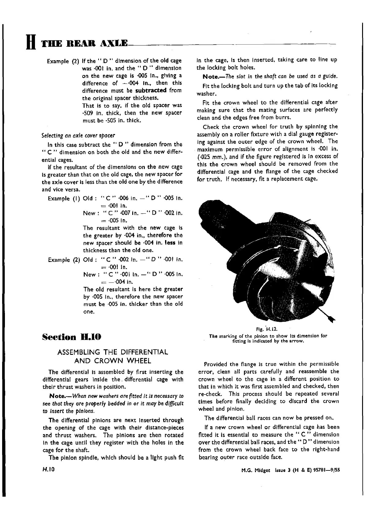
Fig.·H.12.
The marking of the pinion to show
lts dimension for
fitting is
j ndlcated by the
arrow.
Provided
the
flange is
true
within
the
permissible
error,
clean all
parts
carefully and
reassemble
the
crown
wheel
to
the
cage in a
different
position
to
that
in which it was first assembled and
checked,
then
re-check. This
process
shouId be
repeated
seve ral
times
before finally decldlng
to
discard
the
crown
wheel
and pinion.
The
differential ball races can
now
be pressed
on.
If a
new
crown
wheel
or
differential cage has
been
fitted it is essential
to
measure
the"
C " dimension
over
the
differential ball races, and
the"
D"
dimension
from
the
crown
wheel
back face
to
the
right-hand
bearing
outer
race
outside
face.
M.G. Midget lssue 3 (H & E) 95781-9{55
Wishvilles Classic
Automobile Library

 Loading...


