------------------TBE
ENGINE A
Take off
the
gearbox
top
cover
complete
and
secure
a piece of cardboard
over
'the
gearbox
opening in
order
to
prevent
dirt
reaching
the
Inside.
Note.-Great
care
must be taken
when
removing
or
refitting the gear
change
lever and Its
housing.
If the
selector
shaft is
withdrawn
past the
~rst
stop the syn-
chromesh
mechanism
will slide apart and the
synchro-
ballswill
drop
to the
bottom
of the
gearbox.
This
means
the complete
gearbox
must be
dismantled.
Later boxes
are
fitted with an
extended
1st and 3rd
selector
shaft with a retaining
clrdlp
at
the
forward
end which
overcomes
this.
Unscrew
the
screws round
the
pedal
draught
excluder
and disconnect
the
speedometer
drive.
Detach
the
forward
end
of
the
propeller
shaft.
marking
the
flanges so
that
they
can be reassembled
in
the
same position.
On
LHD models it Is necessary
to
disconnect and
lift
the
steering
column
clear
(see
Section A.3).
Disconnect
the
rear
engine mounting and place a
sling
round
the
unit,
just
behind
the
front
mounting
and also
just
forward of
the
flywheel houstng.
Remove
the
unit by lifting It forward and upward.
taking
care
to
disengage
the
steady link from
lu
bracket.
Note.-See
Sectlon
A,38
for
adjustment of engine
mounting.
Section
A.32
REMOVAL
AND
REPLACEMENT OF
FLYWHEEL
In
order
to
take off
the
flywheel
the
engine and
gearbox
unit
should be
removed
from
the
car as
detailed In Section
A.31.
It is advised
not
to
disturb
the
flywheel unneces-
sarily
as It Is essential for it
to
run absolutely
true.
Remove
the
clutch as detailed in Section
E.2.
Remove
the
locking
wire
on
the
flywheel fixing bolts.
Take
out
the
fiXing bolts.
Pull off
the
flywheel with asuitable
extractor,
taking
care
not
to
damage
the
locati ng dowels.
Replacement is a reversal of
this
process.
Check
the
flywheel for accuracy. It should be no
more
th an
·0021
n. ('05 mrn.)
out
of
truth
at any point
when
rotated
with a dial gauge in
contact
with
the
cI
utch face.
Section
A.33
REMOVAL
AND
REPLACEMENT OF
CRANKSHAFT
(Engine
out
of
Chassis)
Remove
the
sump
as detailed
under
SectIon A.2.
Remove
the
fan drtvtng pulley and timing chain
case
~
detailed
under
Section A.I8.
Remove
the
timing chain as detailed
under
Section
A.20.
Remove
the
pistons and connecting rods as detailed
under
Section
A.IO.
Remove
the
two
securing nuts from each main
bearing
cap and
remove
the
caps and bearings.
Note.-It
Is
advisable
to mark
each
bearing
cap and
bearing
to ensure their correct
position
for
subsequent
replacement.
Remove
the
crankshaft and flywheel.
If necessary remove
the
flywheel as detailed
under
Section A.32.
but
only
If necessary.
Replacement of
the
crankshaft is
carried
OUt
In
the
reverse
manner
to
that
detailed
for
removal,
but
before doing so, clean
the
oilways In
the
crankshaft.
In
order
to
clean
out
the
ollways in
the
crankcase.
the
camshaft, filter,
011
pump and pipes should be
removed.
All bearings and
other
parts should be cleaned
carefully before replacement, and care must be
taken
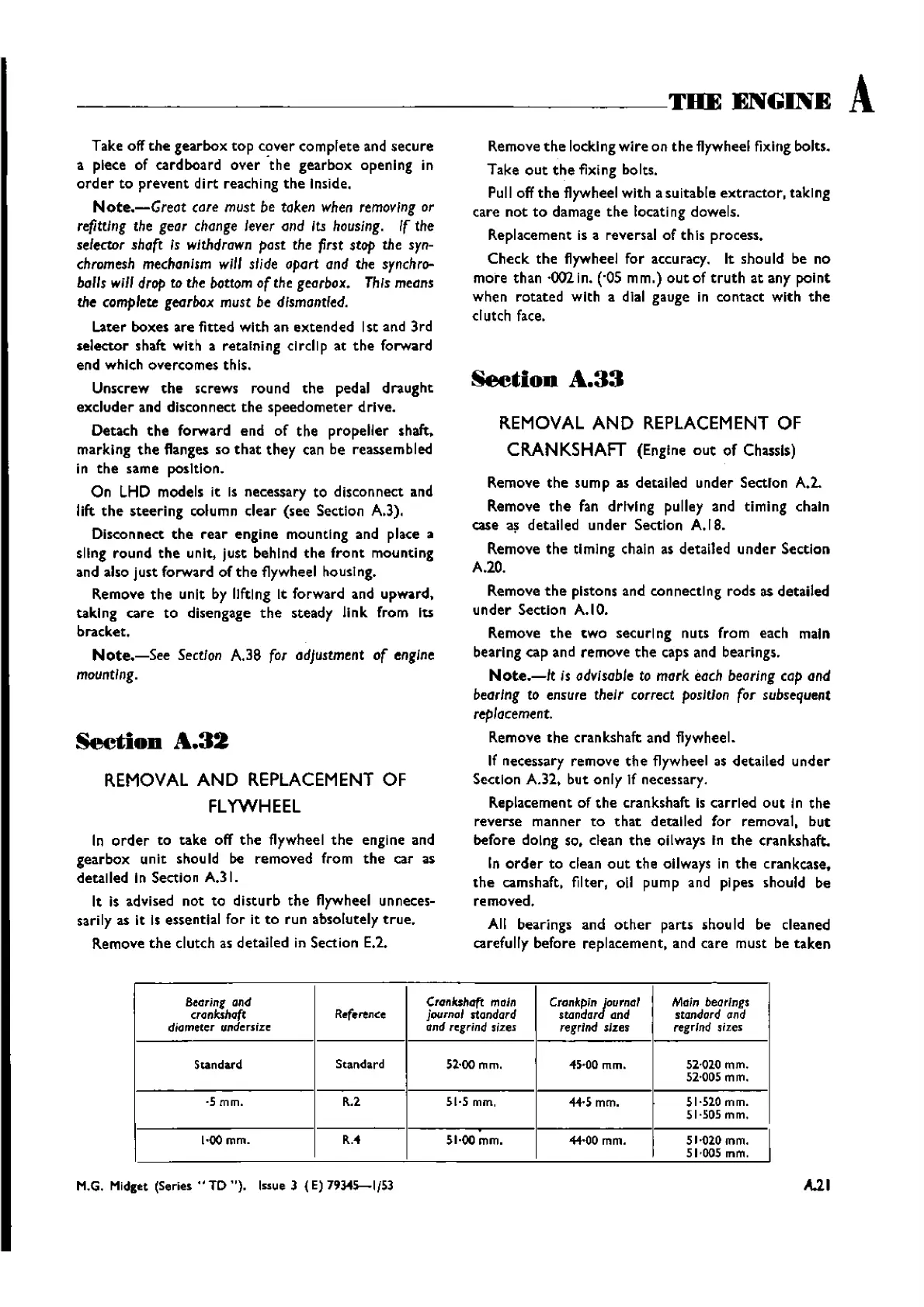
BeGring
and
Crankshaft
main
Crankpin
Journal
Main bearings
crankshaft Reference journal standard
standar and standard and
diameler
undersize
and regrind sizes
regrind
sizes
regrind 5;zes
Standard
Standard
52·00 mm. 45·00 mm. 52·020 mm.
52·005 mm.
·5mm.
R.2 51·5 mm.
44·5 mm.
51·510 mm.
51·505 rnm,
,
I
I·oomm.
R.-4
51·00 mm.
-44·00mm.
51·020mm.
51·005 mm.
M.G. Midget
(Series"
TO
").
Issue
3 (E) 79345-1{53
A.21
Wishvilles Classic
Automobile Library

 Loading...


