-------------------TIIE
ENGINE A
The
gear-type
011
pump draws
011
from
the
sump
through
a
gau%e
strainer
which picks up
the
oil Just
above
the
bottom
of
the
sump. Any sludge formed In
the
011
Is
thus
allowed every
opportunity
to
settle
to
the
bottom.
An oU
pressure
relief valve, of
the
spring-loaded
ball type.
controls
a passage formed in
the
oil pump
bottom
cover
casting
between
the
suction and delivery
sides
of
the
pump gears. (See Fig. A.7.)
The
spring
is non-adjustable. and Is
set
to
allow
the
valve
to
by-pass
at
50-70 lb.
per
sq. in. (3·5-5-0 kg./cm.
i
) .
This provides a normal working pressure of from
40
to
.045
lb.
per
sq. in. (2·a
to
3·2 kg./crn.!). But so
long as a reasonable
pressure
Is indicated it may be
taken
that
the
circulating system Is workIng
satls-
fae:torily.
The
011
from
the
pump Is delivered
to
the
full-
flow oil filter and
then
to
the
011
gallery, whence
It Is
distributed
through
the
engine.
There
are
two
possible ways from
the
pump. First,
the
normal one.
through
tile filter
deaning
element. Second. an
emergency path
through
another
spring-leaded relief
valve housed in
the
cylinder block behind
the
pump
body.
straight
Into
the
011
gallery. The spring of
the
by-pass valve is such
that,
provided
the
filter is
attended
to
periodically (fit new all filter after
the
first 3,000 miles
or
SOOO
kilometres and subsequently
every
6,000 miles
or
10000
kilometres on engines
prior
to
No.
14224
and new filter
element
on engines
from No. 14224 onwards),
the
valve remains per-
manently closed. Should
the
filter become clogged,
however,
the
by-pass valve will open and allow
unfiltered oil
to
reach
the
engine.
From
the
oil filter
outlet
the
oil is delivered Into
the
Interna.l oil gallery j n
the
side of
the
cyli
nder
block.
Three
drilled passages from this gallery pipe lead
the
all
to
the
camshaft and crankshaft bearings.
TakIng
these
passages in
order,
counting from
the
front, No. I feeds
the
front
maln bearing and
the
camshaft
front
bearing.
The
front
main bearing feeds
No. I big-end bearing through a groove
cut
In
the
white
metal and a passage drilled in
the
crank web,
which. in
turn,
feeds No. I cylinder wall through
the
spray hole drilled In
the
right-hand side of
the
big-end
and by splash from
the
surplus oil exudIng from
the
bearing. A feed is also taken from
the
front
main
bearing
to
the
automatic chain tensioner.
The
camshaft front bearing has a forward leak
passage
to
the
camshaft chain wheel
thrust
face. and
from
there
passes
through
three
diagonal holes in
the
gear wheel boss
to
the
inside of
the
wheel rim,
where
centrifugal action forces it through radial holes
onto
the
chain links.
The
three
diagonal holes In
the
sprocket
are
covered by a baffle plate. This plate
M.G. Midgut
(Series"
TO
").
bsue
3
(E)
8/52
ensures
that
the
011
Is deflected
to
the radial holes at
low engine speeds.
Passage
No.2
feeds
the
camshaft
centre
bearing
and
the
centre
main bearing. The
centre
main bear-
Ing feeds Nos. 2 and 3 big-end bearings by diagonal
drtllings in
the
crankshaft and also lubricates
the
cylinder walls as already described.
Passage
No.3
feeds
the
rear
main bearing and
the
rear
camshaft bearing. The
rear
main bearing also feeds
No.4
big-end bearing and
the
cylinder walls
through
diagonal drillings.
A vertical pipe at
the
rear
end of
the
011
gallery
feeds
011
to
the
rocker-shaft
through
passages drilled
in
the
cylinder head
to
register
with
a hole drilled
in
the
rear
rocker-shaft
support,
which communi-
cates with
the
inside of
the
hollow rocker-shaft.
The
rocker-shaft Is drilled at each
rocker
position
to
feed oil
to
the
bearings, and all whIch passes
the
bushes
finds Its way down
the
push-rod tunnels and drain
passages
to
the
sump.
Note.-When
the engine Is
first
storted up and the
oil is cold, higher
01/
pressure than
normal
will be
indicated by the
gauge.
It Is mainly
for
this reason that
a gauge
covering
a
large
range
of
pressure
readings
Is
provided,
and the risk of
damage
to the Instrument
Is
thus
reduced
to a minimum.
In
the
event
of
the
oil gauge beIng damaged,
or
ceasing
to
function correctly, It must be renewed as
soon as possible.
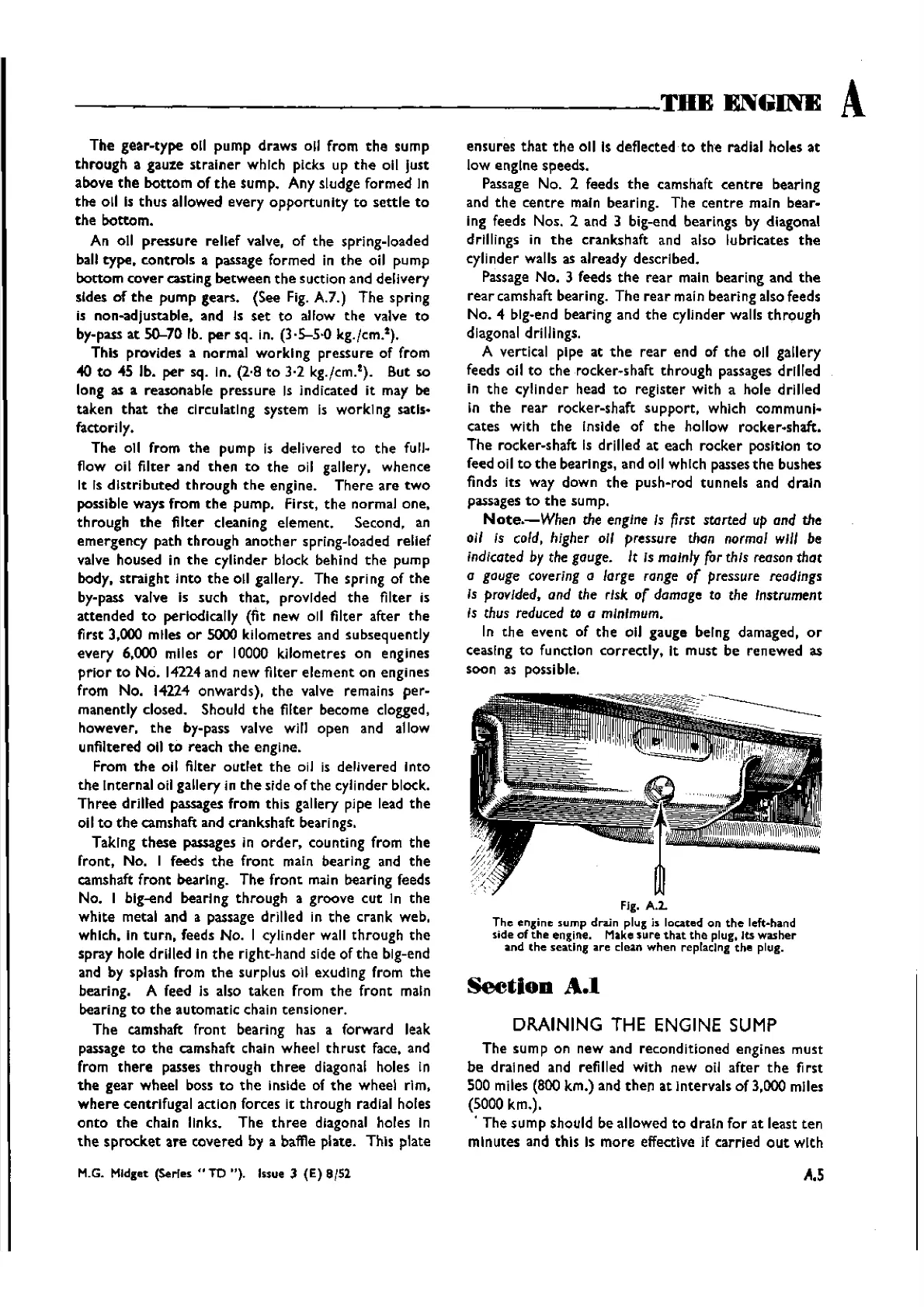
FIg. A.2.
The
engine sump drain plug is located on
the
left-hand
side
of
the
engine. Make
sure
that
the
plug, Its
washer
and
the
seating are clean when replacIng
the
plug.
Section
A.I
DRAINING THE ENGINE
SUMP
The
sump on new and reconditioned engines must
be drained and refilled with new oil
after
the
first
sao
miles (800 km.) and
then
at intervals of 3,000 miles
(5000krn.)•
. The
sump
should be allowed to drain
for
at least
ten
minutes and this is
more
effective jf
tarried
out
wIth
A.S
Wishvilles Classic
Automobile Library

 Loading...


