spring washer is not a reliable conductor, and the brass
tag
must
therefore bear directly against the head ofthe
screw.
All
four
connections, namely
the
two
ends
of
the
earthing
tag and
the
two
ends of
the
coli, should be
soldered.
The
coil end leading
to
the
terminal
should be
soldered
to
its tag and not
to
the
retainIng
nut. In
the
case of
the
terminal
screw which holds
the
bakelite
cover
in position, similar considerations
apply,
the
assembly being
:-Spring
washer
(I),
wiring tag (2), lead
washer
(3), and recessed
nut
(04)
(see Fig. SA). A lead
washer
has been found
necessary at this
point
as some few cases of had
connection have been found.
Under
no circumstances
---THE
FUEL SYSTEM B
2. Flt
the
impact
washer
In
the
recess of
armature.
3. Screw
the
armature
In position.
4. Place
the
eleven gulde rollers in position around
the
armature.
No
jointing
compound
may
be
used
on
the
diaphragm.
5. Hold
the
magnet assembly in
the
left hand, in
an approximately horizontal
posltlon,
6. Push
armature
in with
the
thumb
of
the
right
hand. pushing firmly
but
steadily. If
the
contact
breaker
throws
over.
the
armature
should be screwed in
farther
until it ceases
to
do
so;
It should
then
be unscrewed one-sixth
of a
turn
at a
time,
until a position is found
where
the
contact
breaker
rocker
Just
throws
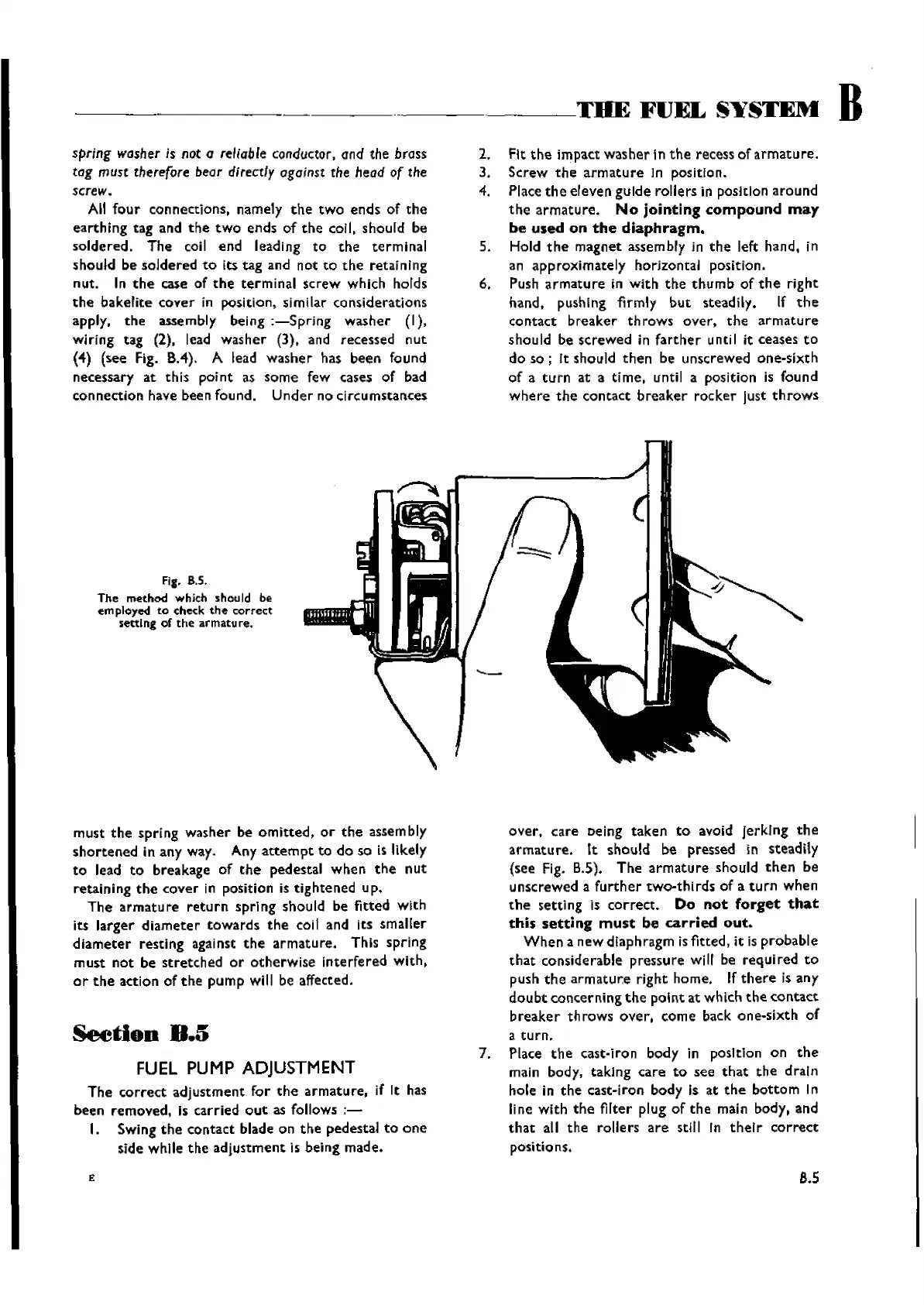
Fig_
B.S.
The
method
whith
should be
employed
to
check
the
correct
setting of the armature.
must
the
spring washer be
omitted,
or
the
assembly
shortened
in any way. Any
attempt
to do so is likely
to
lead
to
breakage of
the
pedestal
when
the
nut
retaining
the
cover
in posltlon is
tightened
up.
The
armature
return
spring
should be fitted with
its
larger
diameter
towards
the
coil and its smaller
diameter
resting against
the
armature.
This spring
must
not
be
stretched
or
otherwise
interfered
with,
or
the
action of
the
pump
will be affected.
SeetiOD
D.5
FUEL
PUMP
ADJUSTMENT
The
correct
adjustment
for
the
armature,
if It has
been removed, Is carried
out
as follows
;-
I. SWing
the
contact blade on
the
pedestal
to
one
side while
the
adjustment
is being made.
£
over.
care
eelng
taken
to
avoid Jerking
the
armature.
It should be pressed in steadily
(see Fig. B.S).
The
armature
should
then
he
unscrewed a
further
two-thirds
of a
turn
when
the
setting is
correct.
Do
not
forget
that
this
setting
must
be
carried
out.
When
a new diaphragm isfitted, it is
probable
that
considerable pressure will be
required
to
push
the
armature
right home. If
there
is any
doubt
concerning
the
point
at which
the
contact
breaker
throws
over,
come back one-sixth of
a
turn.
7. Place
the
cast-iron body in posltlon on
the
main body, takIng
care
to
see
that
the
draln
hole in
the
cast-iron body is at
the
bottom
In
line with
the
filter plug of
the
main body, and
that
all
the
rollers
are
stlll In
thetr
correct
positions.
8.5
Wishvilles Classic
Automobile Library

 Loading...


